
-
Posts
428 -
Joined
-
Last visited
-
Days Won
42
Content Type
Profiles
Forums
Events
Posts posted by Petr Vanek - Robe
-
-
Hello,
this is intentional. This allows manufacturers to publish multiple brands under one manufacturer. If you want these brands not to appear under your manufacturer, then create a new manufacturer or use different user for upload of that brand.
Kind regards
Petr
-
Thank you for the report, i reported it to the team.
-
Defining Wiring Connections for Electrical Devices
To describe connectors and other connection details of attaching of electrical devices that can be wired, dedicated type of Geometry called Wiring Object is used. All specified parameters and details of the Wiring Object are defined in Geometry Type Wiring Object in the GDTF Spec.
In this example, we define connectors for a device which has a Power (Power In and Power Out via Neutrik Powercon True1), DMX (DMX In and DMX Out via XLR 5Pin) and a Network (RJ45 connector).
Pigtail
First we need to indicate physical placement of connectors on the device. This is done in the Geometry tab of the GDTF Builder by adding a Normal Geometry with a model of primitive type "Pigtail". The connectors are typically physically located on the base of the device, so we add it to the Base in our example.
To add the Pigtail:
- select the Base of the device
- click Add Child Geometry
- give it a name Pigtail
- in the Select Model choose New Pigtail
- adjust Dimensions
- select Geometry Type - Normal Geometry
- click OK
- adjust X, Y, Z to position the Pigtail to the appropriate location on the Base
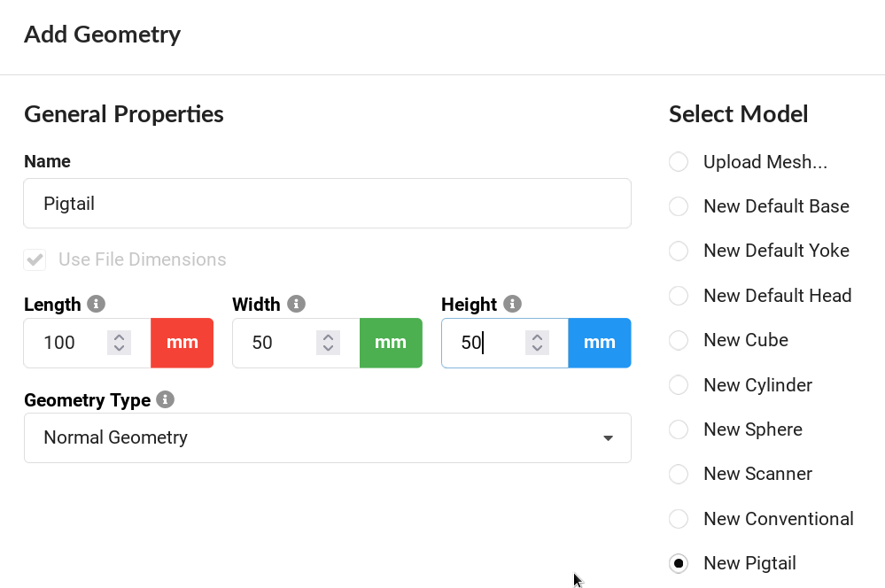
Adding Pigtail screen
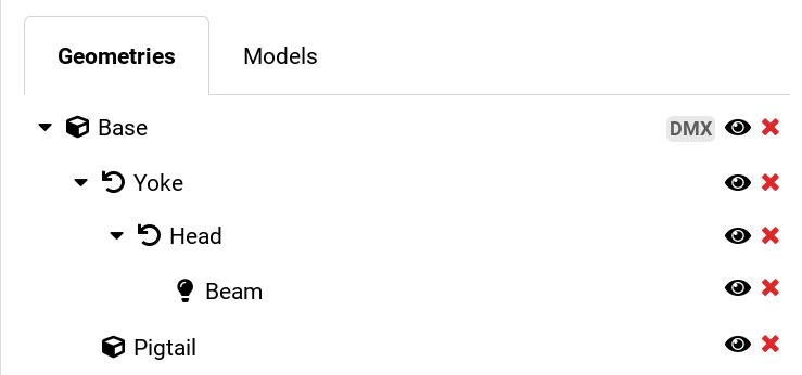
Pigtail is a child of the Base
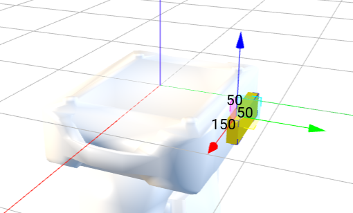
Pigtail positioned to indicate real location of connectors on the device
If the device has more than one panel with connectors, add multiple Pigtails. For example linear products with Input on one end and Output on another end, or a device with Inputs on a base and Outputs on the yoke or head for some attachable accessory.
Connections on the Pigtail are defined by Wiring Object geometry for each connector. All these Wiring Object geometries will be children of the Pigtail.
Wiring Object geometry has the following properties. Not all the following properties are used in all Wiring Objects.
- Name - user friendly name to indicate the connection. Good name could include IN for input, OUT for output. Do not use the Connector Type in the name.
- Connector Type - select the type of used connector or provide new connector type.
- Component Type - the type of the electrical component used, for example Consumer, PowerSource, Input, Output and so on. Some of these Component Types might extend the list of possible properties of the Wiring Object.
- Signal Type - the type of the signal, for example DMX512, AnalogVideo and so on
- Pin Count - the number of available pins of the connector type to connect internal wiring to it
- Signal Layer - this indicates connection between Wiring Objects in the device itself. In one device, all Wiring Geometries that use the same Signal Layer are connected. Special value is 0, which is connecting all Wiring Geometries together.
- Orientation - indicates relative location of this connector on a connection panel
- WireGroup - name of the group to which this wiring object belongs to, for grouping all DMX connectors together by setting the WireGroup to "DMX" for all DMX connectors.
Power Input
We start by defining Powercon True1 Power Input connection for our device:
- Select Pigtail geometry
- click Add Child Geometry
- give it a name Power IN
- in the Select Model choose New Empty Geometry
- select Geometry Type - Wiring Object
And also fill in the properties of the Wiring Object:
- Connector Type - Powercon True1
- Component Type - Consumer
- Signal Type - Power, or leave empty
- Pin Count - 3
- Signal Layer - 1
- Orientation - Top
- WireGroup - Power or leave empty
- Electrical PayLoad - the electrical consumption in Watts.
- Voltage Range Min - the voltage range's minimum value
- Voltage Range Max - the voltage range's maximum value
- Frequency Range Min - the Frequency range's minimum value
- Frequency Range Max - the Frequency range's maximum value
- CosPhi - The Power Factor of the device
- click OK
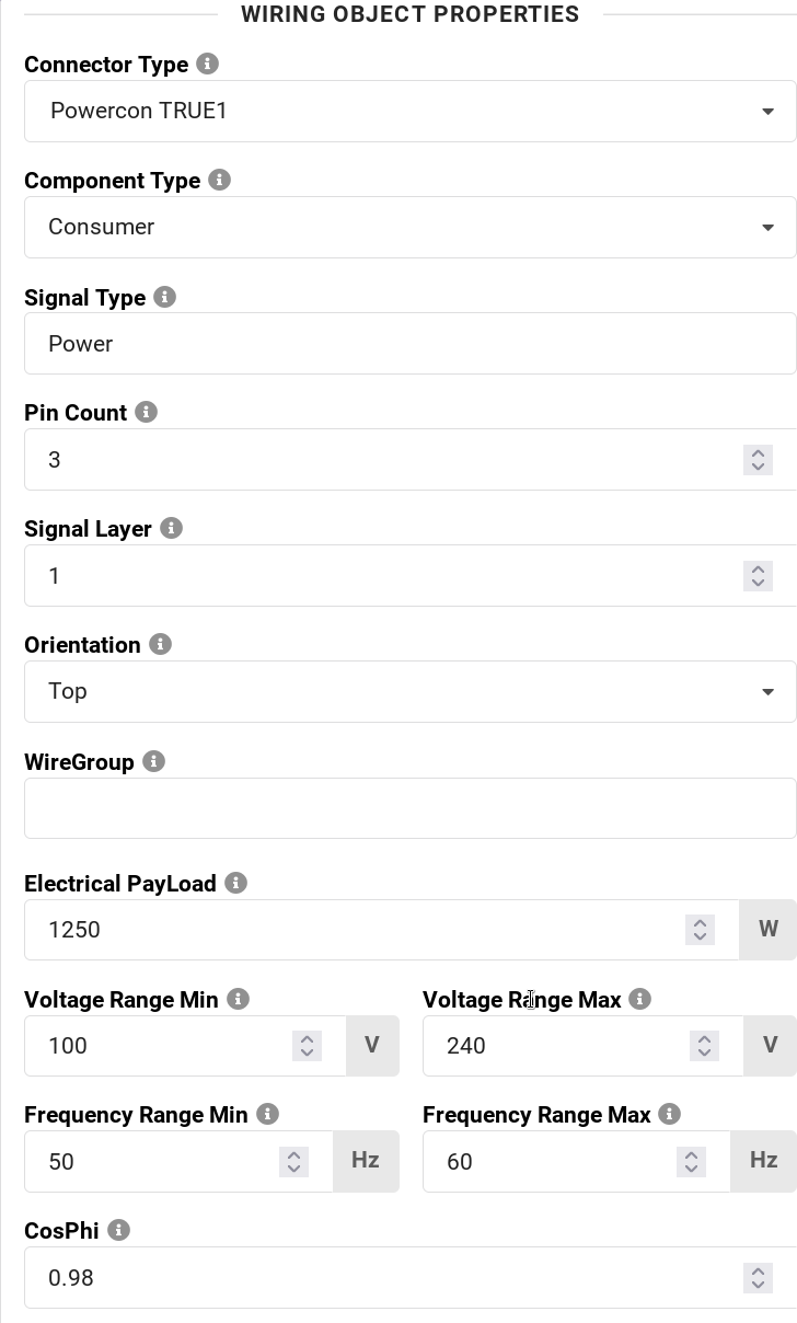
Properties of Power IN Wiring Object
Power Output
Our device allows daisy chaining power from one device to another. We continue by defining Powercon True1 Power Output connection:
- Select Pigtail geometry
- click Add Child Geometry
- give it a name Power OUT
- in the Select Model choose New Empty Geometry
- select Geometry Type - Wiring Object
And also fill in the properties of the Wiring Object:
- Connector Type - Powercon True1
- Component Type - Output
- Signal Type - Power, or leave empty
- Pin Count - 3
- Signal Layer - 1 - this indicates that IN and OUT are connected inside our device
- Orientation - Top
- WireGroup - Power or leave empty
- click OK
DMX Connectors
We can continue by adding DMX connectors. These are typically In and Out, we will use NetworkInput and NetworkOutput as a Component Type, the Signal Type will be DMX512. To indicate that In and Out are connected, we will assign same Signal Layer to both DMX connectors. In case that there are both 3Pin and 5Pin XLR connectors on the device which are typically all connected to each other, all of them will have the same Signal Layer number.
To add 5 Pin XLR DMX In:
- Select Pigtail geometry
- click Add Child Geometry
- give it a name DMX IN
- in the Select Model choose New Empty Geometry
- select Geometry Type - Wiring Object
And also fill in the properties of the Wiring Object:
- Connector Type - 5-pin XLR
- Component Type - NetworkInput
- Signal Type - DMX512
- Pin Count - 5
- Signal Layer - 2
- Orientation - Bottom
- WireGroup - DMX or leave empty
- click OK
To add 5 Pin XLR DMX Out:
- Select Pigtail geometry
- click Add Child Geometry
- give it a name DMX OUT
- in the Select Model choose New Empty Geometry
- select Geometry Type - Wiring Object
And also fill in the properties of the Wiring Object:
- Connector Type - 5-pin XLR
- Component Type - NetworkOutput
- Signal Type - DMX512
- Pin Count - 5
- Signal Layer - 2
- Orientation - Bottom
- WireGroup - DMX or leave empty
- click OK
If the device has also 3 Pin XLR DMX Input and Output, do the same as above, just change the Pin Count to 3. The Signal Layer will be the same if all DMX connectors are connected inside the device.
If the device also has RJ45 network connection, this is how to add it:
- Select Pigtail geometry
- click Add Child Geometry
- give it a name Ethernet
- in the Select Model choose New Empty Geometry
- select Geometry Type - Wiring Object
And also fill in the properties of the Wiring Object:
- Connector Type - 10/100 BaseT ethernet type
- Component Type - NetworkInOut
- Signal Type - can remain empty or mention a specific protocol this output is for, for example Video
- Pin Count - 8
- Signal Layer - 3
- Orientation - Left
- WireGroup - can remain empty, especially if there is only one connector of this type
- click OK
We are done. After adding Power In and Out, DMX 5 pin In and Out and also Ethernet port, this is what the geometry tree will look like:
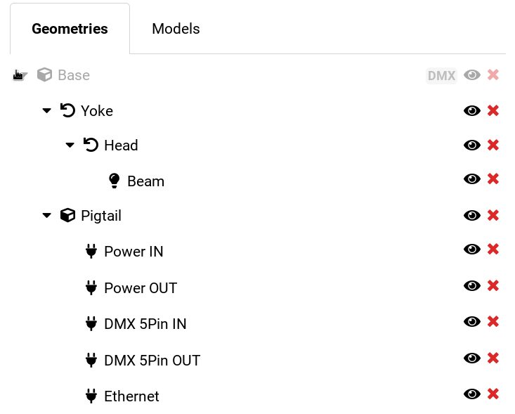
Pigtail with connectors
Hope this helps
Petr
See all Robe Knowledge Sharing Articles.
-
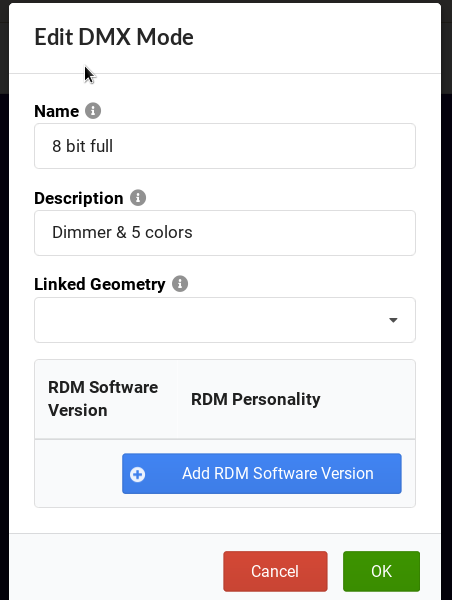
Hello,
you do this by linking a DMX Mode to a geometry tree root:


Hope this helps,
Kind regards
Petr
-
I would suggest to have good connection and good computing device when working with the Builder. Depending on your usecase, you may be transferring lots of data, requiring some reasonable internet quality, also the device will need you decent screen space, it is not a mobile app. The fact that it is built with web technologies is to allow more direct access, not require installation, have better update paths and so on, still it is a complex application and it needs a proper computer to run on.
Kind regards
Petr
-
Hello,
best would be to approach VW directly with questions about their implementation...
Kind regards
Petr
-
39 minutes ago, iLevac said:
I would happily do the GDTF fixture profile and then share it online with both the manufacturer and the community. I feel like asking the manufacturer will take a very long time, but I will give a try. That's unfortunate that manufacturer have better tool than user to create those fixture profile.
I do usually start with a profile that do exist and edit it, but with the online GDTF builder, it's quite limited, I cannot import the DMX profile only or download, edit via a txt or xml file and them upload it back to GDTF. That would be so much more easy if there was a way to edit via text since with the webui that will take forever.
Thanks for the info
iLevac
Manufacturers have the same tool you have - the Builder, here. GDTF is just a zipped folder, you can open it and edit the description.xml by hand or by custom tools...
-
As for the Beams definition, i will have it to be checked, some of the data seems not correct, thank you.
The Min/Max... values are related to DMX Profiles, that is curves defining relation between linear DMX and (nonlinear) behavior of the physical element. This is not physical from/to, that is in the PhysicalFrom/To. The (Minimum Physical Value that will be used for the DMX Profile. Default: Value from PhysicalFrom).
As for the LuminousFlux value in the beam, this is just an indication of the output of the device to have some reference, then there is more precise data, such are the Emitters/Filters sections. As far as spectral power distribution of emitters, all of Robe color measurements are consistent, taken at a consistent distance, taking square root law into consideration and so on, to ensure that spot/wash/linear devices come with measurement that are possible to be used. For more detailed beam description, LDT or IES (or the new TM 30-18 description) will need to be used, which is planned for GDTF for the future. The description of the beam is (say LDT) is still providing an information about one particular setting (for example zoom).
-
Hello and welcome,
i would suggest that you contact the device manufacturer and ask for GDTF from them. What GDTF provides them is a tool do create the file, distribution platform, documentation about the format, documentation about files creation and so on. You could make the files yourself, but then the device manufacturer never knows that there is a need for GDTFs. As far as converting MA2 to a basic GDTF structure, i am not aware of such tool. Given product similarities, i would think it might be more interesting to start from and existing GDTF file for a device from the same manufacturer + product category and modify it for the required device. As for the 3D, convert it to glb, rather then 3DS.
Hope this helps
Petr
-
GDTF does specify the following primitive types: “Undefined”, “Cube”, “Cylinder”, “Sphere”, “Base”, “Yoke”, “Head”, “Scanner”, “Conventional”, “Pigtail”, "Base1_1", "Scanner1_1", "Conventional1_1"; and it also provides models for these primitive types (here) with the exception of the basic 3D shapes like cube, cylinder, sphere and pigtail, which (pigtail), in the default implementation by the GDTF Builder, is being provided by a cube. Again, some internal implementation by specific software will vary slightly as i mentioned, this is why it is better to talk to the vendor directly if needed, as for example getting a precise vertex count depends on the software library you choose to use.
-
I presume you mean the Resource Manager in VectorWorks? Let me add @klinzey here, maybe he has an idea, or knows if this is planned for the future.
Cheers
P.
-
FYI, we have cut some parts of the model and decimated the model slightly more, to get under the MA limit to get their default 3D view with our custom meshes. You can see the result on the Share. Have a good weekend 🙂
-
Interesting... I cannot see where i can set the limit to be below/above 1200 vertices in MA, i only can see Standard/High/... settings, including in their documentation, where can you see this? As per your and mine calculations, the total vertex count of what we provide for the Spiider is still below the recommended 1200 limit, considering the pigtail should be a generic cube, which is what we add when we create the file. On the side note, the GDTF recommended 1200 limit is for a traditional moving head with base, yoke, head and one beam, rather then for a fixture with 19 beams. It is a good conversation, but as this is about specific software behavior, i would suggest that you discuss this behavior of the MA software with MA as i have no inner knowledge of their system...
-
Thank you for confirming that the Spiider comes up OK for you. At the end of the day, we don't control software defaults and even if we try to micro-optimize the Spiider, if you for example add Tarrantula you will have the same issue, so LOD setting will be needed anyways. As far as details of the multiplixel multilayer based devices, this is work in progress for better visualization. You will have to ask MA about the details of their software.
Petr
-
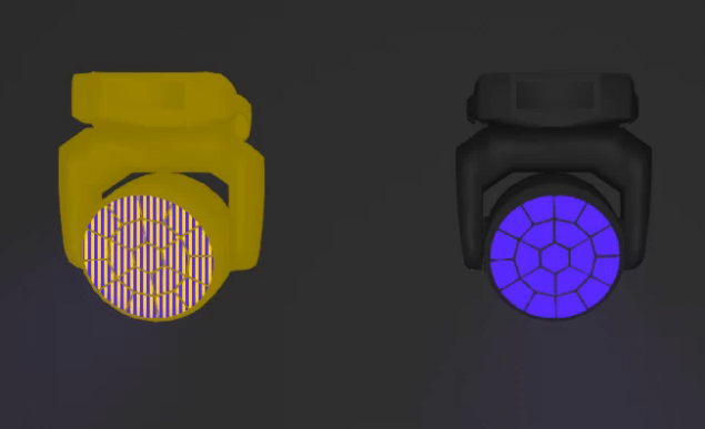
3 hours ago, redmonkey said:
The current version of the Robin Spiider is being visualised as primitive types only on the current version (v1.8.8.2) of MA3 onPC (see attached). Also note thatonly the center pixel is being visualised, not being too familiar with GDTF or MA3 it's unclear to me if that is simply the result of the visualised primitive types or a separate issue.
According to the share, the 3D model has been tested, how is this being tested?
I do wonder about the benefits of creating fixture specific models, it seems that most are very low quality significantly lacking definition of the details to such an extent the model is barely (and in some cases, totally) unrecognisable. I understand the main purpose of the default res of the model is for use by visualisers and as such super detailed models are not required, but, the max 1200 vertex restriction is too limiting in many cases.
> not being too familiar with GDTF or MA3 it's unclear to me
Thank you for your feedback, much appreciated. The GDTF provided limit is more then enough for us to provide nice models and also the lens shapes. And if we needed more, there are now three levels of details in GDTF itself to provide really high quality meshes. The Spiider uses less then 900 vertices:
models/gltf/yoke.glb 202
models/gltf/head.glb 302
models/gltf/pixel3.glb 20
models/gltf/base.glb 298
models/gltf/pixel2.glb 10
models/gltf/pixel1.glb 12
total vertex count: 844As for MA, you need to get at least a bit familiar with how to use the software you want to use for the testing. MA requires you to change level of detail for rendering, as sometimes they change the models to look like packing boxes. Once the setting is done, what you will see is this:
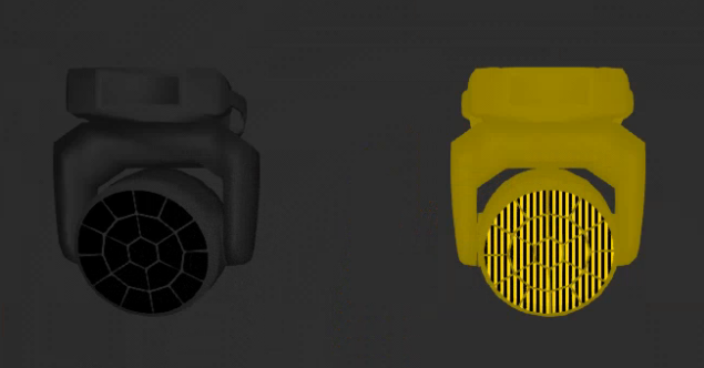
When at full, they look like this:
Hope this helps,
Petr
-
All currently available Robe GDTF files have been converted to use the glTF mesh format, in the form of glb files. You can read more about it here https://gdtf-share.com/user-page?name=Robe+Lighting+s.r.o.&page=home . This change has happened already in October/November, together with many other improvements and changes like converting the Connectors into Wiring Objects, adding 2D and also including the above mentioned more streamlined linking of channels to particular geometries. Let us know in case of any issues.
-
 1
1
-
-
14 hours ago, chrisc said:I can't seem to log into the builder app. It keeps throwing the following error:Failed to log in: 1805 - An unknown error has occurred.I have tried on Firefox, Chrome and Edge with the same issue.Has anyone else encountered this issue or know a way around it?
Signing into the builder seems to work OK here. I would presume that you have forgotten your password, you can reset it on the https://gdtf-share.com/forgot-password link.
Hope this helps
Petr
-
Hello,
if you figure it out, we would also love to know. Also, 5.1 has been crashing consistently on my computer so it's harder to test now.
P.
-
Thank you, reported to developers.
-
Thank you, reported to developers.
-
1
-
-
Hello, post the offending file here please, thank you, P.
-
Hello, sorry about the issue. Does it happen with every type of file? Please post a file and a step by step procedure to replicate it, so we can try to reproduce it. Thank you. P.
-
And Pablo,
just for your information... it may depend on console/software implementation to choose the RDM related field, but for auto matching, Software Version ID from DEVICE_INFO would make sense. For the user matching it, it may be different... so this depends on the implementation.
Have a good weekend,
P.
edited for clarity.
-
Hi Pablo,
you enter the values in hex, this is defined in the DIN Spec, see here all relevant sections (they are close to each other, but i linked them anyways):
https://github.com/mvrdevelopment/spec/blob/main/gdtf-spec.md#rdm-section
https://github.com/mvrdevelopment/spec/blob/main/gdtf-spec.md#softwareversionid
https://github.com/mvrdevelopment/spec/blob/main/gdtf-spec.md#table-72-dmxpersonality
In the DMX mode the software version is a version that is sent via RDM and the RDM Mode Id the ID of the mode your software sends when querying the DMX Modes via RDM.
The software version linked to the dmx mode id in the GDTF builder indicates from which software is this DMX mode available in the fixture.
So for you, it would be, as per the image example above:
Software version 1 (taken from boot software id)
and the 1, 2, 3, 4 for modes Basic, FX, Standard, Extended
Hope this helps
P.

GDTF and MVR Events at PL&S 2023
in Announcements & Newsletters
Posted
If you have the opportunity, please visit the GDTF Booth in Hall12.1 B49A at the Prolight + Sound.
Below if the schedule of GDTF related sessions:
Thursday, 27. April 2023 11:00 – 12:00 in Hall 11 Level 0, Room "Korall": GDTF Open Manufacturer Meeting, details.
Thursday, 27. April 2023 12:00 – 13:00 in Hall 11 Level 0, Room "Korall": GDTF & MVR Manufacturer Training, details.
Floor Plan