File Format Definition
Normative references
The following documents are referred to in the text in such a way that some or all of their content constitutes requirements of this document. For dated references, only the edition cited applies. For undated references, the latest edition of the referenced document (including any amendments) applies.
ANSI E1.54 2015, PLASA Standard for Color Communication in Entertainment Lighting
ANSI/IES TM-30, IES Method for Evaluating Light Source Color Rendition
RFC 4122, A Universally Unique IDentifier (UUID) URN Namespace (available at https://www.ietf.org/rfc/rfc4122.txt)
IEC 61966-2-1:1999, Multimedia systems and equipment - Colour measurement and management - Part 2-1: Colour management - Default RGB colour space - sRGB
ISO 22028-2:2013, Photography and graphic technology - Extended colour encodings for digital image storage, manipulation and interchange - Part 2: Reference output medium metric RGB colour image encoding (ROMM RGB)
RFC 4122, A Universally Unique IDentifier (UUID) URN Namespace1
OpenSoundControl http://opensoundcontrol.org/index.html
Terms and definitions
For the purposes of this document, the following terms and definitions apply. DIN and DKE maintain terminological databases for use in standardization at the following addresses:
- DIN-TERMinologieportal: available at https://www.din.de/go/din-term
- DKE-IEV: available at http://www.dke.de/DKE-IEV
General Device Type Format GDTF
descriptive name of the specification
Fixture Type Attribute
singular mutually exclusive control function Note 1 to entry: Definitions of common attributes can be found in Annex A.
Activation Group
attributes which need to be activated together to gain control over one logical function Note 1 to entry: As example Pan & Tilt are paired to gain control over Position.
Feature
element that’s groups the Fixture Type Attributes into a structured way for easier access and search
Feature Groups
element that’s groups the Fixture Type Features into a logical way for easier access and search
DMXBreak
term used when a fixture needs more than one DMX start address
glTF
file format for three-dimensional scenes and models Note 1 to entry: glTF is the acronym for Graphics Language Transmission Format.
glb
selfcontained binary file format of a glTF scene or model.
Scope
This document specifies the “General Device Type Format”(GDTF), a unified way of listing and describing the hierarchical and logical structure and controls of any type of controllable device (e.g. luminaires, fog machines, etc.) in the lighting and entertainment industry. It will be used as a foundation for the exchange of device data between lighting consoles, CAD and 3D-pre-visualization applications. The purpose of an existing GDTF-file is to reflect the real-world physical components of the devices and to provide control based on this information. It contains and is derived from the 3D geometry (real world or virtual) of the device. This document is only applicable for lighting systems and equipment used in the entertainment industry.
File Format Definition
To describe the device type, a zip file with the extension “*.gdtf” is used. The archive shall contain a description XML file and resource files. Some of the resource files are located in a folder structure. There are two folders defined: “./wheels” and “./models”. The folder “./models” has subfolders for a better structural overview:
- ./models/3ds
- ./models/gltf
- ./models/svg
The description.xml file contains the description of the device type and all DMX modes as well as all firmware revisions of the device.
./description.xml
./thumbnail.png
./thumbnail.svg
./wheels/gobo1.png
./wheels/gobo2.png
./models/3ds/base.3ds
./models/3ds/yoke.3ds
./models/gltf/base.glb
./models/gltf/yoke.glb
./models/3ds_low/base.3ds
./models/3ds_low/yoke.3ds
./models/gltf_low/base.glb
./models/gltf_low/yoke.glb
./models/gltf_high/base.glb
./models/gltf_high/yoke.glb
./models/3ds_high/base.3ds
./models/3ds_high/yoke.3ds
./models/svg/base.svg
./models/svg/yoke.svg
./models/svg_side/base.svg
./models/svg_side/yoke.svg
./models/svg_front/base.svg
./models/svg_front/yoke.svg
The ZIP archive name is specified as follows:
<ManufacturerName>@<FixtureTypeName>@<OptionalComment>
Example: generic@led@comment
UTF-8 has to be used to encode the XML file. Each XML file internally consists of XML nodes. Each XML node could have XML attributes and XML children. Each XML attribute has a value. If a XML attribute is not specified, the default value of this XML attribute will be used. If the XML attribute value is specified as a string, the format of the string will depend on the XML attribute type. All XML attribute types are specified in Table 1.
Table 1 — XML Attribute Value Types
| Value Type | Format | Description |
|---|---|---|
| Uint | Integer | Unsigned integer |
| Int | Integer | Signed integer |
| Hex | Integer | Number in hexadecimal notation; Default value: 0 |
| Float | float | Floating point numeric; Separator: “.” |
| String | Literal | Text |
| Name | restricted Literal | Unique object names; The allowed characters are listed in Annex C Default value: object type with an index in parent. |
| Date | yyyy-mm-ddThh:mm:ss | Date and time corresponding to UTC +00:00 (Coordinated Universal Time): yyyy – year, mm – month, dd – day, hh – hours (24 format), mm – minutes, ss – seconds. Example: “2016-06-21T11:22:48” |
| Node | Name.Name.Name… | Link to an element: “Name” is the value of the attribute “Name” of a defined XML node. The starting point defines each attribute separately. |
| ColorCIE | floatx, floaty,floatY | CIE color representation xyY 1931 |
| Vector3 | {float,float,float} | Vector with 3 float components |
| Matrix | {float,float,float,float} {float,float,float,float} {float,float,float,float} {float,float,float,float} | The transformation matrix consists 4 x 4 floats. Stored in a row-major order. For example, each row of the matrix is stored as a 4- component vector. The mathematical definition of the matrix is in a column-major order. For example, the matrix rotation is stored in the first three columns, and the translation is stored in the 4th column. The metric system consists of the Right- handed Cartesian Coordinates XYZ: X – from left (-X) to right (+X), Y – from the outside of the monitor (-Y) to the inside of the monitor (+Y), Z – from bottom (-Z) to top (+Z). 0,0,0 – center base. |
| Rotation | {float, float, float} {float, float, float} {float, float, float} | Rotation matrix, consist of 3*3 floats. Stored as row-major matrix, i.e. each row of the matrix is stored as a 3-component vector. Mathematical definition of the matrix is column-major, i.e. the matrix rotation is stored in the three columns. Metric system, right-handed Cartesian coordinates XYZ: X – from left (-X) to right (+X), Y – from the outside of the monitor (-Y) to the inside of the monitor (+Y), Z – from the bottom (-Z) to the top (+Z). |
| Enum | Literal | Possible values are predefined. |
| DMXAddress | Int, Alternative format: Universe.Address | Absolute DMX address (size 4 bytes); Alternative format: Universe – integer universe number, starting with 1; Address: address within universe from 1 to 512. Format: integer |
| DMXValue | Uint/n for ByteMirroring values Uint/ns for ByteShifting values | Special type to define DMX value where n is the byte count. The byte count can be individually specified without depending on the resolution of the DMX Channel. By default byte mirroring is used for the conversion. So 255/1 in a 16 bit channel will result in 65535. You can use the byte shifting operator to use byte shifting for the conversion. So 255/1s in a 16 bit channel will result in 65280. |
| GUID | XXXXXXXX-XXXX-XXXX-XXXX-XXXXXXXXXXXX | Unique ID corresponding to RFC 4122: X–1 digit in hexadecimal notation. Example: “308EA87D-7164-42DE-8106-A6D273F57A51”. |
| Resource | String | File name of the resource file without extension and without subfolder. |
| Pixel | Pixel | Integer value representing one Pixel inside a MediaFile. Pixel count starts with zero in the top left corner. |
The first XML node is always the XML description node: <?xml version="1.0" encoding="UTF-8"?>
The second XML node is the GDTF node. The attribute of this node is the
DataVersion: <GDTF DataVersion="1.2">
The example above shows the XML node for GDTF version 1.2.
Table 2. GDTF Node Attributes
| XML Attribute Name | Value Type | Description |
|---|---|---|
| DataVersion | UInt.UInt | The DataVersion attribute defines the minimal version of compatibility. The Version format is “Major.Minor”, where major and minor is Uint with size 1 byte. |
Fixture Type Node
The FixtureType node is the starting point of the description of the fixture type within the XML file. The defined Fixture Type Node attributes of the fixture type are specified in table 3.
Table 3. Fixture Type Node Attributes
| XML Attribute Name | Value Type | Description |
|---|---|---|
| Name | Name | Name of the fixture type. As it is based on Name, it is safe for parsing. |
| ShortName | String | Shortened name of the fixture type. Non detailed version or an abbreviation. Can use any characters or symbols. |
| LongName | String | Detailed, complete name of the fixture type, can include any characters or extra symbols. |
| Manufacturer | String | Manufacturer of the fixture type. |
| Description | String | Description of the fixture type. |
| FixtureTypeID | GUID | Unique number of the fixture type. |
| Thumbnail | Resource | Optional. File name without extension containing description of the thumbnail. Use the following as a resource file: - png file to provide the rasterized picture. Maximum resolution of picture: 1024x1024 - svg file to provide the vector graphic. - These resource files are located in the root directory of the zip file. |
| ThumbnailOffsetX | Int | Horizontal offset in pixels from the top left of the viewbox to the insertion point on a label. Default value: 0 |
| ThumbnailOffsetY | Int | Vertical offset in pixels from the top left of the viewbox to the insertion point on a label. Default value: 0 |
| RefFT | GUID | Optional. GUID of the referenced fixture type. |
| CanHaveChildren | Enum | Describes if it is possible to mount other devices to this device. Value: “Yes”, “No”. Default value: “Yes” |
Fixture type node children are specified in table 4.
Table 4. Fixture Type Node Children
| Child Node | Mandatory | Description |
|---|---|---|
| AttributeDefinitions | Yes | Defines all Fixture Type Attributes that are used in the fixture type. |
| Wheels | No | Defines the physical or virtual color wheels, gobo wheels, media server content and others. |
| PhysicalDescriptions | No | Contains additional physical descriptions. |
| Models | No | Contains models of physically separated parts of the device. |
| Geometries | Yes | Describes physically separated parts of the device. |
| DMXModes | Yes | Contains descriptions of the DMX modes. |
| Revisions | No | Describes the history of the fixture type. |
| FTPresets | No | Is used to transfer user-defined and fixture type specific presets to other show files. |
| Protocols | No | Is used to specify supported protocols. |
One or more sections could be empty or missing, but the order of sections is mandatory as specified in table 4.
Attribute Definitions
General
This section defines the attribute definitions for the Fixture Type Attributes.
Note 1: More information on the definitions of attributes can be found in Annex A “Attribute Definitions”.
Note 2: All currently defined Fixture Type Attributes can be found in Annex B “Attribute Listing”.
Note 3: All currently defined activation groups can be found in Annex B “Attribute Listing”.
Note 4: All currently defined feature groups can be found in Annex B “Attribute Listing”.
The current attribute definition node does not have any XML attributes
(XML node <AttributeDefinitions>). Children of the attribute definition
are specified in table 5.
Table 5. Attribute Definition Children
| XML node | Mandatory | Description |
|---|---|---|
| ActivationGroups | No | Defines which attributes are to be activated together. For example, Pan and Tilt are in the same activation group. |
| FeatureGroups | Yes | Describes the logical grouping of attributes. For example, Gobo 1 and Gobo 2 are grouped in the feature Gobo of the feature group Gobo. |
| Attributes | Yes | List of Fixture Type Attributes that are used. Predefindes fixtury type attributes can be found in Annex A. |
Activation Groups
General
This section defines groups of Fixture Type Attributes that are intended to be used together.
Example: Usually Pan and Tilt are Fixture Type Attributes that shall be activated together to be able to store and recreate any position.
The current activation groups node does not have any XML attributes (XML
node <ActivationGroups>). As children it can have a list of a
activation group.
Activation Group
This section defines the activation group Attributes (XML node
<ActivationGroup>). Currently defined XML attributes of the activation
group are specified in table 6.
Table 6. Activation Group Attributes
| XML Attribute Name | Value Type | Description |
|---|---|---|
| Name | Name | The unique name of the activation group. |
The activation group does not have any children.
Feature Groups
General
This section defines the logical grouping of Fixture Type Attributes
(XML node <FeatureGroups>).
Note 1: A feature group can contain more than one logical control unit. A feature group Position shall contain PanTilt and XYZ as separate Feature.
Note 2: Usually Pan and Tilt create a logical unit to enable position control, so they must be grouped in a Feature PanTilt.
As children the feature groups has a list of a feature group.
Feature Group
General
This section defines the feature group (XML node <FeatureGroup>). The
currently defined XML attributes of the feature group are specified in
table 7.
Table 7. Feature Group Attributes
| XML Attribute Name | Value Type | Description |
|---|---|---|
| Name | Name | The unique name of the feature group. |
| Pretty | String | The pretty name of the feature group. |
As children the feature group has a list of a feature.
Feature
This section defines the feature (XML node <Feature>). The currently
defined XML attributes of the feature are specified in table
8.
Table 8. Feature Attributes
| XML Attribute Name | Value Type | Description |
|---|---|---|
| Name | Name | The unique name of the feature. |
The feature does not have any children.
Attributes
General
This section defines the Fixture Type Attributes (XML node
<Attributes>). As children the attributes node has a list of a
attributes.
Attribute
This section defines the Fixture Type Attribute (XML node <Attribute>).
The currently defined XML attributes of the attribute Node are specified
in table 9.
Table 9. XML Attributes of the Attribute
| XML Attribute Name | Value Type | Description |
|---|---|---|
| Name | Name | The unique name of the attribute. |
| Pretty | String | The pretty name of the attribute . |
| ActivationGroup | Node | Optional link to the activation group. The starting point is the activation groups node. |
| Feature | Node | Link to the corresponding feature. The starting point is the feature groups node. |
| MainAttribute | Node | Optional link to the main attribute. The starting point is the attribute node. |
| PhysicalUnit | Enum | The currently defined unit values are: “None”, “Percent”, “Length” (m), “Mass” (kg), “Time” (s), “Temperature” (K), “LuminousIntensity”(cd), “Angle” (degree), “Force” (N), “Frequency” (Hz), “Current” (A), “Voltage” (V), “Power” (W), “Energy” (J), “Area” (m2), “Volume” (m3), “Speed” (m/s), “Acceleration” (m/s2), “AngularSpeed” (degree/s), “AngularAccc” (degree/s2), “WaveLength” (nm), “ColorComponent”. Default: “None”. |
| Color | ColorCIE | Optional. Defines the color for the attribute. |
As children the attribute node has a list of a subphysical units.
Subphysical Unit
This section defines the Attribute Subphysical Unit (XML node <SubPhysicalUnit>).
The currently defined XML attributes of the subphysical unit are specified in table 10.
Table 10. XML Attributes of the Subphysical Unit
| XML Attribute Name | Value Type | Description |
|---|---|---|
| Type | Enum | The currently defined values are: “PlacementOffset”, “Amplitude”, “AmplitudeMin”, “AmplitudeMax”, “Duration”, “DutyCycle”, “TimeOffset”, “MinimumOpening”, “Value”, “RatioHorizontal”, “RatioVertical”. |
| PhysicalUnit | Enum | The currently defined unit values are: “None”, “Percent”, “Length” (m), “Mass” (kg), “Time” (s), “Temperature” (K), “LuminousIntensity”(cd), “Angle” (degree), “Force” (N), “Frequency” (Hz), “Current” (A), “Voltage” (V), “Power” (W), “Energy” (J), “Area” (m2), “Volume” (m3), “Speed” (m/s), “Acceleration” (m/s2), “AngularSpeed” (degree/s), “AngularAccc” (degree/s2), “WaveLength” (nm), “ColorComponent”. Default: “None”. |
| PhysicalFrom | Float | The default physical from of the subphysical unit; Unit: as defined in PhysicalUnit; Default value: 0 |
| PhysicalTo | Float | The default physical to of the subphysical unit; Unit: as defined in PhysicalUnit; Default value: 1 |
The subphysical unit does not have any children.
Wheel Collect
General
This section defines all physical or virtual wheels of the device. It
currently does not have any XML attributes (XML node <Wheels>). As
children wheel collect can have a list of a wheels.
Note 1: Physical or virtual wheels represent the changes to the light beam within the device. Typically color, gobo, prism, animation, content and others are described by wheels.
Wheel
General
Each wheel describes a single physical or virtual wheel of the fixture
type. If the real device has wheels you can change, then all wheel
configurations have to be described. Wheel has the following XML node:
<Wheel>. The currently defined XML attributes of the wheel are specified
in table 11.
Table 11. Wheel Attributes
| XML Attribute Name | Value Type | Description |
|---|---|---|
| Name | Name | The unique name of the wheel |
As children, Wheel has a list of wheel slots.
Wheel Slot
General
The wheel slot represents a slot on the wheel (XML node <Slot>). The
currently defined XML attributes of the wheel slot are specified in
table 12.
Table 12. Wheel Slot Attributes
| XML Attribute Name | Value Type | Description |
|---|---|---|
| Name | Name | The unique name of the wheel slot |
| Color | ColorCIE | Color of the wheel slot, Default value: {0.3127, 0.3290, 100.0 } (white) For Y give relative value compared to overall output defined in property Luminous Flux of related Beam Geometry (transmissive case). |
| Filter | Node | Optional. Link to filter in the physical description; Do not define color if filter is used; Starting point: Filter Collect |
| MediaFileName | Resource | Optional. PNG file name without extension containing image for specific gobos etc. - Maximum resolution of picture: 1024x1024 - Recommended resolution of gobo: 256x256 - Recommended resolution of animation wheel: 256x256 These resource files are located in a folder called ./wheels in the zip archive. Default value: empty. |
Note 1: More information on the definitions of images used in wheel slots to visualize gobos, animation wheels or color wheels can be found in Annex E “Wheel Slot Image Definition”.
The link between a slot and a channel set is done via the wheel slot index. The wheel slot index of a slot is derived from the order of a wheel’s slots. The wheel slot index is normalized to 1.
If the wheel slot has a prism, it has to have one or several children called prism facet. If the wheel slot has an AnimationWheel, it has to have one child called Animation Wheel.
Prism Facet
This section can only be defined for the prism wheel slot and has a
description for the prism facet (XML node <Facet>). The currently
defined XML attributes of the prism facet are specified in table
13.
Table 13. Wheel Slot Attributes
| XML Attribute Name | Value Type | Description |
|---|---|---|
| Color | ColorCIE | Color of prism facet, Default value: {0.3127, 0.3290, 100.0 } (white) |
| Rotation | Rotation | Specify the rotation, translation and scaling for the facet. |
The prism facet cannot have any children.
Animation System
This section can only be defined for the animation system disk and it
describes the animation system behavior (XML node <AnimationSystem>).
The currently defined XML attributes of the AnimationSystem are
specified in table 14.
Table 14. AnimationSystem Attributes
| XML Attribute Name | Value Type | Description |
|---|---|---|
| P1 | Array of Float | First Point of the Spline describing the path of animation system in the beam in relation to the middle of the Media File; Array of two floats; Separator of values is “,”; First Float is X-axis and second is Y-axis. |
| P2 | Array of Float | Second Point of the Spline describing the path of animation system in the beam in relation to the middle of the Media File; Array of two floats; Separator of values is “,”; First Float is X-axis and second is Y-axis. |
| P3 | Array of Float | Third Point of the Spline describing the path of animation system in the beam in relation to the middle of the Media File; Array of two floats; Separator of values is “,”; First Float is X-axis and second is Y-axis. |
| Radius | Float | Radius of the circle that defines the section of the animation system which will be shown in the beam |
The AnimationSystem cannot have any children.
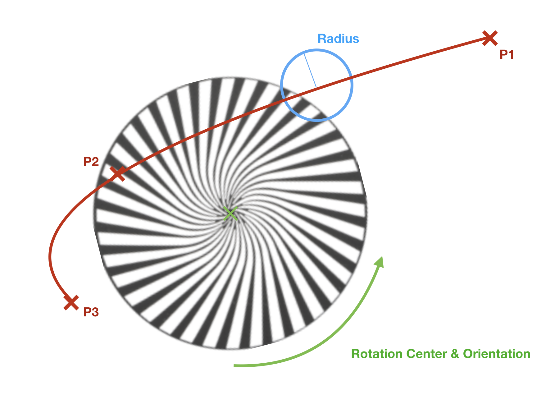
Example of an animation system
Physical Descriptions
General
This section describes the physical constitution of the device. It
currently does not have any XML Attributes (XML node
<PhysicalDescriptions>). Children of Physical Description are specified
in table 15.
Table 15. Physical Description Children
| XML node | Mandatory | Description |
|---|---|---|
| Emitters | No | Describes device emitters |
| Filters | No | Describes device filters |
| ColorSpace | No | Describes device default color space |
| AdditionalColorSpaces | No | Describes additional device color spaces |
| Gamuts | No | Describes device gamuts |
| DMXProfiles | No | Describes nonlinear correlation between DMX input and physical output of a channel. |
| CRIs | No | Describes color rendering with IES TM-30-15 (99 color samples). |
| Connectors | No | Obsolete now. See Geometry Collect, WiringObject. Describes physical connectors of the device. |
| Properties | No | Describes physical properties of the device. |
Emitter Collect
General
This section contains the description of the emitters. Emitter Collect
defines additive mixing of light sources, such as LEDs and tungsten
lamps with permanently fitted filters. It currently does not have any
XML Attributes (XML node <Emitters>). As children the emitter collect
has a list of a emitter.
Emitter
This section defines the description of the emitter (XML node
Table 16. Emitter Attributes
| XML Attribute Name | Value Type | Description |
|---|---|---|
| Name | Name | Unique Name of the emitter |
| Color | ColorCIE | Approximate absolute color point if applicable. Omit for non-visible emitters (eg., UV). For Y give relative value compared to overall output defined in property Luminous Flux of related Beam Geometry (transmissive case). |
| DominantWaveLength | Float | Required if color is omitted, otherwise it is optional. Dominant wavelength of the LED. |
| DiodePart | String | Optional. Manufacturer’s part number of the diode. |
As children, the Emitter has a list of measurements.
Filter Collect
General
This section contains the description of the filters. The Filter Collect
defines subtractive mixing of light sources by filters, such as
subtractive mixing flags and media used in physical or virtual Color
Wheels. It currently does not have any XML Attributes (XML node
<Filters>). As children the filter collect has a list of a
filters.
Filter
This section defines the description of the filter (XML node <Filter>).
The currently defined XML attributes of the filter are specified in
table 17.
Table 17. Filter Attributes
| XML Attribute Name | Value Type | Description |
|---|---|---|
| Name | Name | Unique Name of the filter. |
| Color | ColorCIE | Approximate absolute color point when this filter is the only item fully inserted into the beam and the fixture is at maximum intensity. For Y give relative value compared to overall output defined in property Luminous Flux of related Beam Geometry (transmissive case). |
As children the Filter has a list of measurements.
Measurement
General
The measurement defines the relation between the requested output by a
control channel and the physically achieved intensity. XML node for
measurement is <Measurement>. The currently defined XML attributes of
the measurement are specified in table 18.
Table 18. Measurement Attributes
| XML Attribute Name | Value Type | Description |
|---|---|---|
| Physical | Float | For additive color mixing: uniquely given emitter intensity DMX percentage. Value range between > 0 and <= 100. For subtractive color mixing: uniquely given flag insertion DMX percentage. Value range between 0 and 100. |
| LuminousIntensity | Float | Used for additive color mixing: overall candela value for the enclosed set of measurement. |
| Transmission | Float | Used for subtractive color mixing: total amount of lighting energy passed at this insertion percentage. |
| InterpolationTo | Enum | Interpolation scheme from the previous value. The currently defined values are: “Linear”, “Step”, “Log”; Default: Linear |
The order of the measurements corresponds to their ascending physical values.
Additional definition for additive color mixing: It is assumed that the physical value 0 exists and has zero output.
Additional definition for subtractive color mixing: The flag is removed with physical value 0 and it does not affect the beam. Physical value 100 is maximally inserted and affects the beam.
Note 1: Some fixtures may vary in color response. These fixtures define multiple measurement points and corresponding interpolations.
As children the Measurement Collect has an optional list of a measurement point.
Measurement Point
The measurement point defines the energy of a specific wavelength of a
spectrum. The XML node for measurement point is <MeasurementPoint>. The
defined XML attributes of the measurement points are specified in table
19.
It is recommended, but not required, that measurement points are evenly spaced. Regions with minimal light energy can be omitted, but the decisive range of spectrum must be included. Recommended measurement spacing is 1 nm. Measurement spacing should not exceed 4 nm.
Table 19. Measurement Point Attributes
| XML Attribute Name | Value Type | Description |
|---|---|---|
| WaveLength | Float | Center wavelength of measurement (nm). |
| Energy | Float | Lighting energy (W/m2/nm) |
The measurement point does not have any children.
Color Space Collect
General
This section defines color spaces. Currently it does not
have any XML attributes (XML node <AdditionalColorSpaces>). As children, color space collect has a list of a ColorSpace.
Color Space
This section defines the color space that is used for color mixing with
indirect RGB, Hue/Sat, xyY or CMY control input. (XML node
<ColorSpace>). The currently defined XML attributes of the color space
are specified in table 20.
Table 20. Color Space Attributes
| XML Attribute Name | Value Type | Description |
|---|---|---|
| Name | Name | Unique Name of the Color Space. Default Value: “Default”. Note that the name need to be unique for the default colorspace and all color spaces in the AdditionalColorSpaces node. |
| Mode | Enum | Definition of the Color Space that used for the indirect color mixing. The defined values are “Custom”, “sRGB”, “ProPhoto” and “ANSI”. Default Value: “sRGB” |
| Red | ColorCIE | Optional. CIE xyY of the Red Primary; this is used only if the ColorSpace is “Custom”. |
| Green | ColorCIE | Optional. CIE xyY of the Green Primary; this is used only if the ColorSpace is “Custom”. |
| Blue | ColorCIE | Optional. CIE xyY of the Blue Primary; this is used only if the ColorSpace is “Custom”. |
| WhitePoint | ColorCIE | Optional. CIE xyY of the White Point; this is used only if the ColorSpace is “Custom”. |
The predefined modes for the color space XML Attributes are are specified in table 21.
Table 21. Predefined Modes for Color Space Attribute Mode
| Mode | sRGB | ProPhoto | ANSI |
| Description | Adobe sRGB, HDTV IEC 61966-2-1:1999 | Kodak ProPhoto ROMM RGB ISO 22028-2:2013 | ANSI E1.54-2015 |
| Red | 0.6400, 0.3300, 0.2126 | 0.7347, 0.2653 | 0.7347, 0.2653 |
| Green | 0.3000, 0.6000, 0.7152 | 0.1596, 0.8404 | 0.1596, 0.8404 |
| Blue | 0.1500, 0.0600, 0.0722 | 0.0366, 0.0001 | 0.0366, 0.001 |
| WhitePoint | 0.3127, 0.3290, 1.0000 | 0.3457, 0.3585 | 0.4254, 0.4044 |
The color space does not have any children.
Gamut Collect
General
This section defines gamuts. Currently it does not
have any XML attributes (XML node <Gamuts>). As children, gamut collect has a list of a Gamut.
Gamut
This section defines the color gamut of the fixture (XML node <Gamut>), which is the set of attainable colors by the fixture. The currently defined XML attributes of a gamut
are specified in table 22.
Table 22. Gamut Attributes
| XML Attribute Name | Value Type | Description |
|---|---|---|
| Name | Name | Unique Name of the Gamut. |
| Points | Array of ColorCIE | Set of points defining the vertice of the gamut’s polygon. |
The gamut does not have any children.
DMX Profile Collect
General
This section defines DMX profile descriptions. Currently it does not
have any XML attributes (XML node <DMXProfiles>). As children DMX
profile collect has a list of DMX profiles.
DMX Profile
This section defines the DMX profile description (XML node
<DMXProfile>). The currently defined XML attributes of the DMX profile
are specified in table 23.
Table 23. DMX Profile Attributes
| XML Attribute Name | Value Type | Description |
|---|---|---|
| Name | Name | Unique name of the DMX profile |
As children a DMX Profile has a list of point.
Point
This section contains points to define the DMX profile (XML node <Point>). The currently defined XML attributes of a point
are specified in table 24.
Table 24. Point Attributes
| XML Attribute Name | Value Type | Description |
|---|---|---|
| DMXPercentage | Float | DMX percentage of the point; Unit: Percentage; Default value: 0 |
| CFC0 | Float | Cubic Function Coefficient for x⁰; Default value: 0 |
| CFC1 | Float | Cubic Function Coefficient for x; Default value: 0 |
| CFC2 | Float | Cubic Function Coefficient for x²; Default value: 0 |
| CFC3 | Float | Cubic Function Coefficient for x³; Default value: 0 |
Find the Point with the biggest DMXPercentage below or equal x. If there is none, the output is expected to be 0.
Output(x) = CFC3 * (x - DMXPercent)³ + CFC2 * (x - DMXPercent)² + CFC1 * (x - DMXPercent) + CFC0
Here is an example where the output follows a function f for 75% of the DMX Range and another function g for the last 25%. The Point attributes are given to illustrate how they are defined.
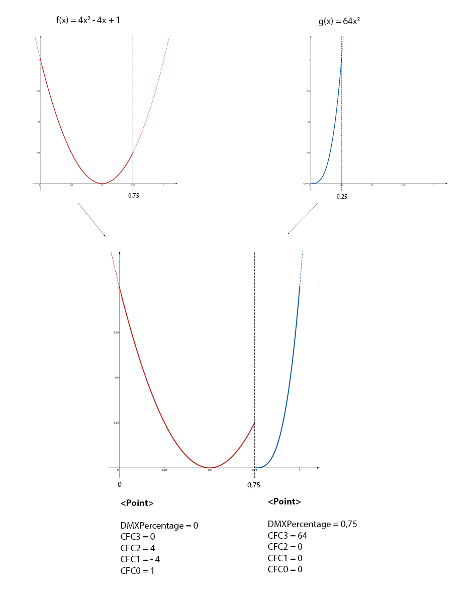
Figure 1. DMXProfile example
A Point does not have any children.
Color Rendering Index Collect
General
This section contains TM-30-15 Fidelity Index (Rf) for 99 color samples.
Currently it does not have any XML attributes (XML node <CRIs>). As
children, CRIs has a list of CRI groups.
Color Rendering Index Group
General
This section contains CRIs for a single color temperature (XML node
<CRIGroup>). The currently defined XML attributes of the CRI group are
specified in table 25.
Table 25. CRI Group Attributes
| XML Attribute Name | Value Type | Description |
|---|---|---|
| ColorTemperature | Float | Color temperature; Default value: 6000; Unit: Kelvin |
As children, the CRIGroup has an optional list of Color Rendering Index.
Color Rendering Index
This section defines the CRI for one of the 99 color samples (XML node
<CRI>). The currently defined XML attributes of the measurement point
are specified in table 26.
Table 26. CRI Attributes
| XML Attribute Name | Value Type | Description |
|---|---|---|
| CES | Enum | Color sample. The defined values are “CES01”, “CES02”, … “CES99”. Default Value “CES01" |
| ColorRenderingIndex | UInt | The color rendering index for this sample. Size: 1 byte; Default value: 100 |
The color rendering index does not have any children.
Connector Collect
General
This section defined the physical connectors and is kept for backwards compatibility. From DIN SPEC 15800:2022 or GDTF v1.2 onwards physical connectors shall be decribed as WiringObjects in the Geometry Collect.
It currently does not have any XML attributes (XML node <Connectors>). As children, the Connector Collect has a list of a connectors.
Connector
See Geometry Collect WiringObject. For easier transition find below the equivalent of the WiringObject.
This section defines the connector (XML node <Connector>). The currently
defined XML attributes of the connector are specified in table
27.
Table 27. Connector Attributes
| XML Attribute Name | Value Type | Description |
|---|---|---|
| Name | Name | Unique Name of the connector. Now: Geometry Type WiringObject, XML Attribute: Name |
| Type | Name | The type of the connector. Find a list of predefined types in Annex D. Now: Geometry Type WiringObject, XML Attribute: ConnectorType. |
| DMXBreak | Uint | Optional. Defines to which DMX Break this connector belongs to. Obsolete now. |
| Gender | Int | Connectors where the addition of the Gender value equal 0, can be connected; Default value: 0; Male Connectors are -1, Female are +1, Universal are 0. Obsolete now. |
| Length | Float | Defines the length of the connector’s wire in meters. “0” means that there is no cable and the connector is build into the housing. Default value “0”. Obsolete now. |
The connector does not have any children.
Properties Collect
General
This section defines the general properties of the device type (XML node
<Properties>). The Properties Collect currently does not have any XML
attributes. The currently defined children nodes of properties collect
are specified in table 28.
Table 28. Properties Collect
| XML node | Amount | Description |
|---|---|---|
| OperatingTemperature | 0 or 1 | Temperature range in which the device can be operated. |
| Weight | 0 or 1 | Weight of the device including all accessories. |
| PowerConsumption | Any | Power information for a given connector. |
| LegHeight | 0 or 1 | Height of the legs. |
OperatingTemperature
This section defines the ambient operating temperature range (XML node
<OperatingTemperature>). The currently defined XML attributes of the
OperatingTemperature are specified in table 29.
Table 29. Operating Temperature Attributes
| XML Attribute Name | Value Type | Description |
|---|---|---|
| Low | Float | Lowest temperature the device can be operated. Unit: °C. Default value: 0 |
| High | Float | Highest temperature the device can be operated. Unit: °C. Default value: 40 |
The OperatingTemperature currently does not have any children.
Weight
This section defines the overall weight of the device (XML node
<Weight>). The currently defined XML attributes of the weight are
specified in table 30.
Table 30. Weight Attributes
| XML Attribute Name | Value Type | Description |
|---|---|---|
| Value | Float | Weight of the device including all accessories. Unit: kilogram. Default value: 0 |
The weight currently does not have any children.
LegHeight
This section defines the height of the legs (XML node <LegHeight>). The
currently defined XML attributes of the LegHeight are specified in
table 31.
Table 31. Leg Height Attributes
| XML Attribute Name | Value Type | Description |
|---|---|---|
| Value | Float | Defines height of the legs - distance between the floor and the bottom base plate. Unit: meter. Default value: 0 |
The LegHeight currently does not have any children.
Model Collect
General
Each device is divided into smaller parts: body, yoke, head and so on.
These are called geometries. Each geometry has a separate model
description and a physical description. Model collect contains model
descriptions of the fixture parts. The model collect currently does not
have any XML attributes (XML node <Models>). As children, Model Collect
has a list of model.
Model
This section defines the type and dimensions of the model (XML node
<Model>). The currently defined XML attributes of the model are
specified in table 32.
Table 32. Model Attributes
| XML Attribute Name | Value Type | Description |
|---|---|---|
| Name | Name | The unique name of the model |
| Length | Float | Unit: meter; Default value: 0 |
| Width | Float | Unit: meter; Default value: 0 |
| Height | Float | Unit: meter; Default value: 0 |
| PrimitiveType | Enum | Type of 3D model; The currently defined values are: “Undefined”, “Cube”, “Cylinder”, “Sphere”, “Base”, “Yoke”, “Head”, “Scanner”, “Conventional”, “Pigtail”, “Base1_1”, “Scanner1_1”, “Conventional1_1”; TODO Default value: “Undefined” |
| File | Resource | Optional. File name without extension and without subfolder containing description of the model. Use the following as a resource file: - 3DS or GLB to file to provide 3D model. - SVG file to provide the 2D symbol. It is possible to add several files with the same name but different formats. Preferable format for the 3D model is GLTF. The resource files are located in subfolders of a folder called ./models. The names of the subfolders correspond to the file format of the resource files (3ds, step, svg). The path for 3ds files would be ./models/3ds. For glb files, it would be ./models/gltf.Software that is utilizing GDTF files should always be able to read both 3ds and GlTF file formats and should be able to write at least one of these formats. It is preferable that only one type of 3D model file formats is used within one GDTF file. |
| SVGOffsetX | Float | Offset in X from the 0,0 point to the desired insertion point of the top view svg. Unit based on the SVG. Default value: 0 |
| SVGOffsetY | Float | Offset in Y from the 0,0 point to the desired insertion point of the top view svg. Unit based on the SVG. Default value: 0 |
| SVGSideOffsetX | Float | Offset in X from the 0,0 point to the desired insertion point of the side view svg. Unit based on the SVG. Default value: 0 |
| SVGSideOffsetY | Float | Offset in Y from the 0,0 point to the desired insertion point of the side view svg. Unit based on the SVG. Default value: 0 |
| SVGFrontOffsetX | Float | Offset in X from the 0,0 point to the desired insertion point of the front view svg. Unit based on the SVG. Default value: 0 |
| SVGFrontOffsetY | Float | Offset in Y from the 0,0 point to the desired insertion point of the front view svg. Unit based on the SVG. Default value: 0 |
The model currently does not have any children.
All models of a device combined should not exceed a maximum vertices count of 1200 for the default mesh level of detail.
There are three level of details that you can define:
Table 33. Mesh level of detail
| LOD | Description | Folder 3DS / gltf |
|---|---|---|
| Low | Optional; This is the mesh for fixtures that are far away from the camera. It should have 30% of the the vertexes from the default mesh vertex count. | 3ds_low / gltf_low |
| Default | This is the default mesh that is used for real time visualization in preprogramming tool. It should have the minimum vertex count possible, while still looking like the fixture in 3D. | 3ds / gltf |
| High | Optional; This is high quality mesh targeting non-realtime applications, where the vertex count is not that important. There is no limit for the vertex count. | 3ds_high / gltf_high |
Low and High meshes definitions are optional. Place the file with the same name in the defined folder.
The device shall be drawn in a hanging position displaying the front view. That results in the pan axis is Z aligned, and the tilt axis is X aligned.
The metric system consists of the Right-handed Cartesian Coordinates XYZ: X – from left (-X) to right (+X), Y – from the outside of the monitor (-Y) to the inside of the monitor (+Y), Z – from bottom (-Z) to top (+Z). 0,0,0 – center base plate. See Figure 2.

Figure 2. Device in a hanging position – front view
The mesh of each fixture part shall be drawn around its own suspension point. The zero point of a device does not necessarily have to contain the offset related to the yoke, but it must be centered on its axis of rotation. The offset is defined by the geometry and has to be related to its parent geometry and not to the base.
Note 1: In general, the offsets are mostly negative, because the device is displayed in a hanging position.
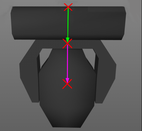
Figure 3. Offsets of the parts
In Figure 3 the green arrow displays the offset of the yoke related to the base. The magenta arrow displays the offset of the head related to the yoke. The offsets are to be defined by the position matrix of the according geometry (table 32). It is important that the axis of rotation of each device part is exactly positioned (see Figure 4).
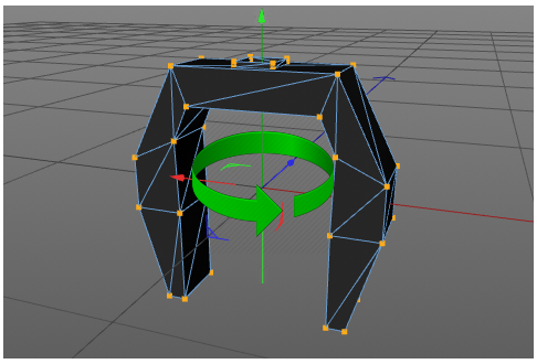
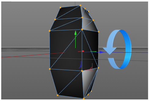
Figure 4. Positions of rotation axis
The dimension XML attributes of model (see table 32) are always used, no matter the scaling and ratio of the mesh file. The mesh is explicitly scaled to this dimension. The length defines the dimension of the model on the X axis, the width on the Y axis and the height on the Z axis.
SVG use viewboxes to align their content. The viewbox is always defined ny the
top left of the bounding box. With the attributes SVG_VIEW_Offset_XY you can
define the insertion point in relation to the view box.
SVG can have background filling. This filling should have the color #C8C8C8. By this color, any software can replace it with another color.
| Type | Description | Folder 3DS / gltf |
|---|---|---|
| Top View | View from top in -Z direction. | svg |
| Front View | View from fron in Y direction | svg_front |
| Side View | View from fron in -X direction | svg_side |

SVG images should be drawn in a 1:1 scale to the actual device. Use mm as base unit. Scaling operation from 3D meshes will not be applied to the SVG informations
Regarding glTF Files
The used glTF files should follow these requirements:
- Use the
glbbinary format - Only use the 2.0 version
- Do not use extension
- Do not use animations
- Only use jpeg or png texture resource
- all vertex attributes are
GL_FLOAT
Regarding SVG Files
- Use SVG 1.1 spec
- Don’t embed bitmap images.
- Align the viewbox to the top left of the device
Geometry Collect
General
The physical description of the device parts is defined in the geometry
collect. Geometry collect can contain a separate geometry or a tree of
geometries. The geometry collect currently does not have any XML
attributes (XML node <Geometries>). The currently defined children nodes
of geometry collect are specified in table 34.
Table 34. Geometry Children Types
| XML node | Amount | Description |
|---|---|---|
| Geometry | Any | General Geometry. |
| Axis | Any | Geometry with axis. |
| FilterBeam | Any | Geometry with a beam filter. |
| FilterColor | Any | Geometry with color filter. |
| FilterGobo | Any | Geometry with gobo. |
| FilterShaper | Any | Geometry with shaper. |
| Beam | Any | Geometry that describes a light output to project. |
| MediaServerLayer | Any | Geometry that describes a media representation layer of a media device. |
| MediaServerCamera | Any | Geometry that describes a camera or output layer of a media device. |
| MediaServerMaster | Any | Geometry that describes a master control layer of a media device. |
| Display | Any | Geometry that describes a surface to display visual media. |
| GeometryReference | Any | Reference to already described geometries. |
| Laser | Any | Geometry with a laser light output. |
| WiringObject | Any | Geometry that describes an internal wiring for power or data. |
| Inventory | Any | Geometry that describes an additional item that can be used for a fixture (like a rain cover). |
| Structure | Any | Geometry that describes the internal framing of an object (like members). |
| Support | Any | Geometry that describes a support like a base plate or a hoist. |
| Magnet | Any | Geometry that describes a point where other geometries should be attached. |
Note 1: Position the geometry in it’s “Default” position. This is defined by the Default Value from the DMX Channel that controls the position of that geometry.
General Geometry
It is a basic geometry type without specification (XML node <Geometry>).
The currently defined XML attributes of the geometry are specified in
table 35.
Table 35. Geometry Attributes
| XML Attribute Name | Value Type | Description |
|---|---|---|
| Name | Name | The unique name of geometry. Recommendation for conventional is “Body”. Recommendation for a geometry that is representing the base housing of a moving head is “Base”. |
| Model | Name | Link to the corresponding model. |
| Position | Matrix | Relative position of geometry; Default value: Identity Matrix |
The geometry has the same children types as the geometry collect (see table 34).
Geometry Type Axis
This type of geometry defines device parts with a rotation axis (XML
node <Axis>). The currently defined XML attributes of the axis are
specified in table 36.
Table 36. Axis Attributes
| XML Attribute Name | Value Type | Description |
|---|---|---|
| Name | Name | The unique name of the geometry. Recommendation for an axis-geometry is “Yoke”. Recommendation for an axis-geometry representing the lamp housing of a moving head is “Head”. Note: The Head of a moving head is usually mounted to the Yoke. |
| Model | Name | Link to the corresponding model. Matrix |
| Position | Matrix | Relative position of geometry; Default value: Identity Matrix |
The axis has the same children types as the geometry collect (see table 34).
Geometry Type Beam Filter
This type of geometry defines device parts with a beam filter (XML node
<FilterBeam>). The currently defined XML attributes of the beam filter
are specified in table 37.
Table 37. Beam Filter Attributes
| XML Attribute Name | Value Type | Description |
|---|---|---|
| Name | Name | The unique name of the geometry. Recommendation for beam filter limiting the diffusion of light is “BarnDoor”. Recommendation for beam filter adjusting the diameter of the beam is “Iris”. Note: BarnDoor and Iris are usually mounted to conventional. |
| Model | Name | Link to the corresponding model. |
| Position | Matrix | Relative position of geometry; Default value: Identity Matrix |
The beam filter has the same children types as the geometry collect (see table 34).
Geometry Type Color Filter
This type of geometry is used to describe device parts which have a
color filter (XML node <FilterColor>). The currently defined XML
attributes of the color filter are specified in table 38.
Table 38. Color Filter Attributes
| XML Attribute Name | Value Type | Description |
|---|---|---|
| Name | Name | The unique name of geometry. Recommendation for filter of a color or mechanical color changer is “FilterColor”. Note: FilterColor is usually mounted to conventional. |
| Model | Name | Link to the corresponding model. |
| Position | Matrix | Relative position of geometry; Default value: Identity Matrix |
The color filter has the same children types as the geometry collect (see table 34).
Geometry Type Gobo Filter
This type of geometry is used to describe device parts which have gobo
wheels (XML node <FilterGobo>). The currently defined XML attributes of
the gobo filter are specified in table 39.
Table 39. Gobo Filter Attributes
| XML Attribute Name | Value Type | Description |
|---|---|---|
| Name | Name | The unique name of the geometry. Recommendation for filter of a gobo or mechanical gobo changer is “FilterGobo”. Note: FilterGobo is usually mounted to conventional. |
| Model | Name | Link to the corresponding model. |
| Position | Matrix | Relative position of geometry; Default value: Identity Matrix |
The gobo filter has the same children types as the geometry collect (see table 34).
Geometry Type Shaper Filter
This type of geometry is used to describe device parts which have a
shaper (XML node <FilterShaper>). The currently defined XML attributes
of the shaper filter are specified in table 40.
Table 40. Shaper Filter Attributes
| XML Attribute Name | Value Type | Description |
|---|---|---|
| Name | Name | The unique name of the geometry; Recommendation for filter used to form the beam to a framed, triangular, or trapezoid shape, is “Shaper”. Note: Shaper is usually mounted to conventional. |
| Model | Name | Link to the corresponding model. |
| Position | Matrix | Relative position of geometry; Default value: Identity Matrix |
The shaper filter has the same children types as the geometry collect (see table 34).
Geometry Type Beam
This type of geometry is used to describe device parts which have a
light source (XML node <Beam>). The currently defined XML attributes of
the Beam are specified in table 41.
Table 41. Beam Attributes
| XML Attribute Name | Value Type | Description |
|---|---|---|
| Name | Name | The unique name of the geometry. Recommendation for a light source of a conventional or moving head or a projector is “Beam”. Note 1: Beam is usually mounted to Head or Body. Recommendation for a self-emitting single light source is “Pixel”. Note 2: Pixel is usually mounted to Head or Body. Recommendation for a number of Pixel that are controlled at the same time is “Array”. Note 3: Array is usually mounted to Head or Body. Recommendation for a light source of a moving mirror is “Mirror”. Note 4: Mirror is usually mounted to Yoke. |
| Model | Name | Link to the corresponding model. |
| Position | Matrix | Relative position of geometry; Default value: Identity Matrix |
| LampType | Enum | Defines type of the light source; The currently defined types are: Discharge, Tungsten, Halogen, LED; Default value “Discharge” |
| PowerConsumption | Float | Power consumption; Default value: 1000; Unit: Watt |
| LuminousFlux | Float | Intensity of all the represented light emitters; Default value: 10000; Unit: lumen |
| ColorTemperature | Float | Color temperature; Default value: 6000; Unit: kelvin |
| BeamAngle | Float | Beam angle; Default value: 25.0; Unit: degree |
| FieldAngle | Float | Field angle; Default value: 25.0; Unit: degree |
| ThrowRatio | Float | Throw Ratio of the lens for BeamType Rectangle; Default value: 1; Unit: None |
| RectangleRatio | Float | Ratio from Width to Height of the Rectangle Type Beam; Default value: 1.7777; Unit: None |
| BeamRadius | Float | Beam radius on starting point. Default value: 0.05; Unit: meter. |
| BeamType | Enum | Beam Type; Specified values: “Wash”, “Spot”, “None”, “Rectangle”, “PC”, “Fresnel”, “Glow”. Default value “Wash” |
| ColorRenderingIndex | Uint | The CRI according to TM-30 is a quantitative measure of the ability of the light source showing the object color naturally as it does as daylight reference. Size 1 byte. Default value 100. |
| EmitterSpectrum | Node | Optional link to emitter in the physical description; use this to define the white light source of a subtractive color mixing system. Starting point: Emitter Collect; Default spectrum is a Black-Body with the defined ColorTemperature. |
The beam has the same children types as the geometry collect (see table 34).
Use the Geometry Type “Beam” to describe the position of the fixture’s light output (usually the position of the lens) and not the position of the light source inside the device. The origin of the Geometry Type “Beam” is the origin of the rendered beam. The origin of the Geometry Type “Beam” should not be covered by any faces of other geometries in order to not block the rendered beam.
The <BeamType> describes how the Beam will be rendered.
“Wash”, “Fresnel”, “PC”- A conical beam with soft edges and softened field projection.
“Spot” - A conical beam with hard edges.
“Rectangle” - A pyramid-shaped beam with hard edges.
“None”, “Glow” - No beam will be drawn, only the geometry will emit light itself.
The beam geometry emits its light into negative Z direction (and Y-up).
Geometry Type Media Server Layer
This type of geometry is used to describe the layer of a media device
that is used for representation of media files (XML node
<MediaServerLayer>). The currently defined XML attributes of the media
server layer are specified in table 42.
Table 42. Media Server Layer Attributes
| XML Attribute Name | Value Type | Description |
|---|---|---|
| Name | Name | The unique name of the geometry. |
| Model | Name | Link to the corresponding model that will be used to display the alignment in media server space. |
| Position | Matrix | Relative position of geometry; Default value: Identity Matrix |
The media server layer has the same children types as the geometry collect (see table 34).
Geometry Type Media Server Camera
This type of geometry is used to describe the camera or output of a
media device (XML node <MediaServerCamera>). The currently defined XML
attributes of the media server camera are specified in table
43.
Table 43. Media Server Camera Attributes
| XML Attribute Name | Value Type | Description |
|---|---|---|
| Name | Name | The unique name of the geometry. |
| Model | Name | Link to the corresponding model that will be used to display the alignment in media server space. |
| Position | Matrix | Relative position of geometry; Default value: Identity Matrix |
The media server camera has the same children types as the geometry collect (see table 34).
The media server camera-view points into the positive Y-direction (and Z-up).
Geometry Type Media Server Master
This type of geometry is used to describe the master control of one or
several media devices (XML node <MediaServerMaster>). The currently
defined XML attributes of the media server master are specified in
table 44.
Table 44. Media Server Master Attributes
| XML Attribute Name | Value Type | Description |
|---|---|---|
| Name | Name | The unique name of the geometry. |
| Model | Name | Link to the corresponding model. |
| Position | Matrix | Relative position of geometry; Default value: Identity Matrix |
The media server master has the same children types as the geometry collect (see table 34).
Geometry Type Display
This type of geometry is used to describe a self-emitting surface which
is used to display visual media (XML node <Display>). The currently
defined XML attributes of the display are specified in table 45.
Table 45. Display Attributes
| XML Attribute Name | Value Type | Description |
|---|---|---|
| Name | Name | The unique name of the geometry. |
| Model | Name | Link to the corresponding model. |
| Position | Matrix | Relative position of geometry; Default value: Identity Matrix |
| Texture | Resource | Name of the mapped texture in Model file that will be swapped out for the media resource. |
The display has the same children types as the geometry collect (see table 34).
Geometry Type Laser
General
This type of geometry is used to describe the position of a laser’s
light output (XML node <Laser>). The currently
defined XML attributes of the laser are specified in table 46.
Table 46. Laser Attributes
| XML Attribute Name | Value Type | |
|---|---|---|
| Name | Name | The unique name of the geometry. |
| Model | Name | Link to the corresponding model. |
| Position | Matrix | Relative position of geometry; Default value: Identity Matrix |
| ColorType | Enum | The currently defined unit values are: “RGB”, “SingleWaveLength”, Default: RGB. |
| Color | Float | Required if ColorType is “SingleWaveLength”; Unit:nm (nanometers) |
| OutputStrength | Float | Output Strength of the Laser; Unit: Watt |
| Emitter | Node | Optional link to the emitter group. The starting point is the Emitter Collect. |
| BeamDiameter | Float | Beam diameter where it leaves the projector; Unit: meter |
| BeamDivergenceMin | Float | Minimum beam divergence; Unit: mrad (milliradian) |
| BeamDivergenceMax | Float | Maximum beam divergence; Unit: mrad (milliradian) |
| ScanAnglePan | Float | Possible Total Scan Angle Pan of the beam. Assumes symmetrical output; Unit: Degree |
| ScanAngleTilt | Float | Possible Total Scan Angle Tilt of the beam. Assumes symmetrical output; Unit: Degree |
| ScanSpeed | Float | Speed of the beam; Unit: kilo point per second |
The laser has the same children types as the geometry collect (see table 34).
In addition, it also has a list of supported protocols (XML node <Protocol>) as children.
Protocol
This XML node specifies the protocol for a Laser (XML node <Protocol>). The currently defined XML
attributes of the protocol are specified in table 47.
Table 47 Protocol attributes
| XML Attribute Name | Value Type | Description |
|---|---|---|
| Name | String | Name of the protocol |
The protocol doesn’t have any children.
Geometry Type Reference
General
The Geometry Type Reference is used to describe multiple instances of the same geometry. Example: LED panel with multiple pixels. (XML node ). The currently defined XML attributes of reference are specified in table 48.
Note 1: Geometry Reference also allows easier definition of the DMX Channels for these geometries.
Table 48. Geometry Reference Attributes
| XML Attribute Name | Value Type | Description |
|---|---|---|
| Name | Name | The unique name of geometry. |
| Position | Matrix | Relative position of geometry; Default value: Identity Matrix |
| Geometry | Name | Name of the referenced geometry. Only top level geometries are allowed to be referenced. |
| Model | Name | Optional. Link to the corresponding model. The model only replaces the model of the parent of the referenced geometry. The models of the children of the referenced geometry are not affected. The starting point is Models Collect. If model is not set, the model is taken from the referenced geometry. |
As children, the Geometry Type Reference has a list of breaks. The count of the children depends on the number of different breaks in the DMX channels of the referenced geometry. If the referenced geometry, for example, has DMX channels with DMX break 2 and 4, the geometry reference has to have 2 children. The first child with DMX offset for DMX break 2 and the second child for DMX break 4. If one or more of the DMX channels of the referenced geometry have the special value “Overwrite” as a DMX break, the DMX break for those channels and the DMX offsets need to be defined.
Break
This XML node specifies the DMX offset for the DMX channel of the
referenced geometry (XML node <Break>). The currently defined XML
attributes of the break are specified in table 49.
Table 49. Break Attributes
| XML Attribute Name | Value Type | Description |
|---|---|---|
| DMXOffset | DMXAddress | DMX offset; Default value:1 (Means no offset for the corresponding DMX Channel) |
| DMXBreak | Uint | Defines the unique number of the DMX Break for which the Offset is given. Size: 1 byte; Default value 1. |
Geometry Type Wiring Object
General
This type of geometry is used to describe an electrical device that can be wired (XML node <WiringObject>). The currently
defined XML attributes of a wiring object geometry are specified in table 50.
Table 50. Wiring Object Attributes
| XML Attribute Name | Value Type | Description |
|---|---|---|
| Name | Name | The unique name of the geometry. The name is also the name of the interface to the outside |
| Model | Name | Link to the corresponding model. |
| ConnectorType | Name | The type of the connector. Find a list of predefined types in Annex D. This is not applicable for Component Types Fuses. Custom type of connector can also be defined, for example “Loose End”. |
| Position | Matrix | Relative position of geometry; Default value: Identity Matrix |
| ComponentType | Enum | The type of the electrical component used. Defined values are “Input”, “Output”, “PowerSource”, “Consumer”, “Fuse”, “NetworkProvider”, “NetworkInput”, “NetworkOutput”, “NetworkInOut”. |
| SignalType | String | The type of the signal used. Predefinded values are “Power”, “DMX512”, “Protocol”, “AES”, “AnalogVideo”, “AnalogAudio”. When you have a custom protocol, you can add it here. |
| PinCount | Int | The number of available pins of the connector type to connect internal wiring to it. |
| ElectricalPayLoad | Float | The electrical consumption in Watts. Only for Consumers. Unit: Watt. |
| VoltageRangeMax | Float | The voltage range’s maximum value. Only for Consumers. Unit:volt. |
| VoltageRangeMin | Float | The voltage range’s minimum value. Only for Consumers. Unit: volt. |
| FrequencyRangeMax | Float | The Frequency range’s maximum value. Only for Consumers. Unit: hertz. |
| FrequencyRangeMin | Float | The Frequency range’s minimum value. Only for Consumers. Unit: hertz. |
| MaxPayLoad | Float | The maximum electrical payload that this power source can handle. Only for Power Sources. Unit: voltampere. |
| Voltage | Float | The voltage output that this power source can handle. Only for Power Sources. Unit: volt. |
| SignalLayer | Integer | The layer of the Signal Type. In one device, all wiring geometry that use the same Signal Layers are connected. Special value 0: Connected to all geometries. |
| CosPhi | Float | The Power Factor of the device. Only for consumers. |
| FuseCurrent | Float | The fuse value. Only for fuses. Unit: ampere. |
| FuseRating | Enum | Fuse Rating. Defined values are “B”, “C”, “D”, “K”, “Z”. |
| Orientation | Enum | Where the pins are placed on the object. Defined values are “Left”, “Right”, “Top”, “Bottom”. |
| WireGroup | String | Name of the group to which this wiring object belong. |
The wiring object has the same children types as the geometry
collect (see table 34).
In addition, it also has pin patch (XML node <PinPatch>) children.
Pin Patch
This XML node (XML node <PinPatch>) specifies how the different sockets of its parent
wiring object are connected to the pins of other wiring objects. The currently
defined XML attributes of a pin patch are specified in table 51.
Table 51. Pin Patch Attributes
| XML Attribute Name | Value Type | Description |
|---|---|---|
| ToWiringObject | Node | Link to the wiring object connected through this pin patch. |
| FromPin | Int | The pin number used by the parent wiring object to connect to the targeted wiring object “ToWiringObject”. |
| ToPin | Int | The pin number used by the targeted wiring object “ToWiringObject” to connect to the parent wiring object. |
The pin patch doesn’t have any children.
Geometry Type Inventory
This type of geometry is used to describe a geometry used for the inventory (XML node <Inventory>). The currently
defined XML attributes of an inventory geometry are specified in
table 52.
Table 52. Inventory Attributes
| XML Attribute Name | Value Type | Description |
|---|---|---|
| Name | Name | The unique name of the geometry. |
| Model | Name | Link to the corresponding model. |
| Position | Matrix | Relative position of geometry; Default value: Identity Matrix |
| Count | Int | The default count for new objects. |
The inventory geometry has the same children types as the geometry collect (see table 34).
Geometry Type Structure
This type of geometry is used to describe a structure (XML node <Structure>). The currently
defined XML attributes of a structure geometry are specified in
table 53.
Table 53. Structure Attributes
| XML Attribute Name | Value Type | Description |
|---|---|---|
| Name | Name | The unique name of the geometry. |
| Model | Name | Link to the corresponding model. |
| Position | Matrix | Relative position of geometry; Default value: Identity Matrix |
| LinkedGeometry | Name | The linked geometry. |
| StructureType | Enum | The type of structure. Defined values are “CenterLineBased”, “Detail”. |
| CrossSectionType | Enum | The type of cross section. Defined values are “TrussFramework”, “Tube”. |
| CrossSectionHeight | Float | The height of the cross section. Only for Tubes. Unit: meter. |
| CrossSectionWallThickness | Float | The thickness of the wall of the cross section.Only for Tubes. Unit: meter. |
| TrussCrossSection | String | The name of the truss cross section. Only for Trusses. |
The structure geometry has the same children types as the geometry collect (see table 34).
Geometry Type Support
This type of geometry is used to describe a support (XML node <Support>). The currently
defined XML attributes of a support geometry are specified in
table 54.
Table 54. Support Attributes
| XML Attribute Name | Value Type | Description |
|---|---|---|
| Name | Name | The unique name of the geometry. |
| Model | Name | Link to the corresponding model. |
| Position | Matrix | Relative position of geometry; Default value: Identity Matrix |
| SupportType | Enum | The type of support. Defined values are “Rope”, “GroundSupport”. |
| RopeCrossSection | String | The name of the rope cross section. Only for Ropes. |
| RopeOffset | Vector3 | The Offset of the rope from bottom to top. Only for Ropes. Unit: meter. |
| CapacityX | Float | The allowable force on the X-Axis applied to the object according to the Eurocode. Unit: N. |
| CapacityY | Float | The allowable force on the Y-Axis applied to the object according to the Eurocode. Unit: N. |
| CapacityZ | Float | The allowable force on the Z-Axis applied to the object according to the Eurocode. Unit: N. |
| CapacityXX | Float | The allowable moment around the X-Axis applied to the object according to the Eurocode. Unit: N/m. |
| CapacityYY | Float | The allowable moment around the Y-Axis applied to the object according to the Eurocode. Unit: N/m. |
| CapacityZZ | Float | The allowable moment around the Z-Axis applied to the object according to the Eurocode. Unit: N/m. |
| ResistanceX | Float | The compression ratio for this support along the X-Axis. Unit N/m. Only for Ground Supports. |
| ResistanceY | Float | The compression ratio for this support along the Y-Axis. Unit N/m. Only for Ground Supports. |
| ResistanceZ | Float | The compression ratio for this support along the Z-Axis. Unit N/m. Only for Ground Supports. |
| ResistanceXX | Float | The compression ratio for this support around the X-Axis. Unit N/m. Only for Ground Supports. |
| ResistanceYY | Float | The compression ratio for this support around the Y-Axis. Unit N/m. Only for Ground Supports. |
| ResistanceZZ | Float | The compression ratio for this support around the Z-Axis. Unit N/m. Only for Ground Supports. |
The support geometry has the same children types as the geometry collect (see table 34).
Geometry Type Magnet
This type of geometry is used to describe a magnet, a point where other geometries should be attached (XML node <Magnet>). The currently
defined XML attributes of a magnet geometry are specified in
table 55.
Table 55. Magnet Attributes
| XML Attribute Name | Value Type | Description |
|---|---|---|
| Name | Name | The unique name of the geometry. |
| Model | Name | Link to the corresponding model. |
| Position | Matrix | Relative position of geometry; Default value: Identity Matrix |
The magnet geometry has the same children types as the geometry collect (see table 34).
DMX Mode Collect
General
This section is describes all DMX modes of the device. If firmware
revisions change a DMX footprint, then such revisions should be
specified as new DMX mode. The DMX mode collect currently does not have
any attributes (XML node <DMXModes>). As a child the fixture type DMX
mode collect has DMX modes.
DMX Mode
Each DMX mode describes logical control part of the device in a specific
mode (XML node <DMXMode>). The currently defined XML attributes of the
DMX mode are specified in table 56.
Table 56. DMX Mode Attributes
| XML Attribute Name | Value Type | Description |
|---|---|---|
| Name | Name | The unique name of the DMX mode |
| Description | String | Description of the DMX mode |
| Geometry | Name | Name of the first geometry in the device; Only top level geometries are allowed to be linked. |
DMX mode children are specified in table 57.
Table 57. DMX Mode Children
| XML node | Mandatory | Description |
|---|---|---|
| DMXChannels | Yes | Description of all DMX channels used in the mode |
| Relations | No | Description of relations between channels |
| FTMacros | No | Is used to describe macros of the manufacturer. |
DMX Channel Collect
General
This section defines the DMX footprint of the device. The DMX channel
collect currently does not have any attributes (XML node <DMXChannels>).
As children the DMX channel collect has a list of a DMX
channels.
DMX Channel
General
This section defines the DMX channel (XML node <DMXChannel>). The name
of a DMX channel cannot be user-defined and must consist of a geometry
name and the attribute name of the first logical channel with separator
“_”. In one DMX Mode, this combination needs to be unique. Currently
defined XML attributes of the DMX channel are specified in table
58.
Table 58. DMX Channel Attributes
| XML Attribute Name | Value Type | Description |
|---|---|---|
| DMXBreak | Int | Number of the DMXBreak; Default value: 1; Special value: “Overwrite” – means that this number will be overwritten by Geometry Reference; Size: 4 bytes |
| Offset | Array of Int | Relative addresses of the current DMX channel from highest to least significant; Separator of values is “,”; Special value: “None” – does not have any addresses; Default value: “None”; Size per int: 4 bytes |
| InitialFunction | Node | Link to the channel function that will be activated by default for this DMXChannel. Default value is the first channel function of the first logical function of this DMX channel. |
| Highlight | DMXValue | Highlight value for current channel; Special value: “None”. Default value: “None”. |
| Geometry | Name | Name of the geometry the current channel controls. |
The Geometry should be the place in the tree of geometries where the function
of the DMX Channel (as defined by ChannelFunction) is located either physically
or logically. If the DMX channel doesn’t have a location, put it in the top
level geometry of the geometry tree. Attributes follow a trickle down
principle, so they are inherited from top down.
As children the DMX channel has a list of logical channels.
Logical Channel
The Fixture Type Attribute is assigned to a LogicalChannel and defines
the function of the LogicalChannel. All logical channels that are
children of the same DMX channel are mutually exclusive. In a DMX mode,
only one logical channel with the same attribute can reference the same
geometry at a time. The name of a Logical Channel cannot be user-defined
and is equal to the linked attribute name. The XML node of the logical
channel is <LogicalChannel>. The currently defined XML attributes of the
logical channel are specified in table 59.
Table 59. Logical Channel Attributes
| XML Attribute Name | Value Type | Description |
|---|---|---|
| Attribute | Node | Link to the attribute; The starting point is the Attribute Collect (see Annex A). |
| Snap | Enum | If snap is enabled, the logical channel will not fade between values. Instead, it will jump directly to the new value.; Value: “Yes”, “No”, “On”, “Off”. Default value: “No” |
| Master | Enum | Defines if all the subordinate channel functions react to a Group Control defined by the control system. Values: “None”, “Grand”, “Group”; Default value: “None”. |
| MibFade | Float | Minimum fade time for moves in black action. MibFade is defined for the complete DMX range. Default value: 0; Unit: second |
| DMXChangeTimeLimit | Float | Minimum fade time for the subordinate channel functions to change DMX values by the control system. DMXChangeTimeLimit is defined for the complete DMX range. Default value: 0; Unit: second |
As a child the logical channel has a list of a channel function.
Channel Function
The Fixture Type Attribute is assigned to a Channel Function and defines
the function of its DMX Range. (XML node <ChannelFunction>). The
currently defined XML attributes of channel function are specified in
table 60.
Table 60. Channel Function Attributes
| XML Attribute Name | Value Type | Description |
|---|---|---|
| Name | Name | Unique name; Default value: Name of attribute and number of channel function. |
| Attribute | Node | Link to attribute; Starting point is the attributes node. Default value: “NoFeature”. |
| OriginalAttribute | String | The manufacturer’s original name of the attribute; Default: empty |
| DMXFrom | DMXValue | Start DMX value; The end DMX value is calculated as a DMXFrom of the next channel function – 1 or the maximum value of the DMX channel. Default value: “0/1”. |
| Default | DMXValue | Default DMX value of channel function when activated by the control system. |
| PhysicalFrom | Float | Physical start value; Default value: 0 |
| PhysicalTo | Float | Physical end value; Default value: 1 |
| RealFade | Float | Time in seconds to move from min to max of the Channel Function; Default value: 0 |
| RealAcceleration | Float | Time in seconds to accelerate from stop to maximum velocity; Default value: 0 |
| Wheel | Node | Optional. Link to a wheel; Starting point: Wheel Collect |
| Emitter | Node | Optional. Link to an emitter in the physical description; Starting point: Emitter Collect |
| Filter | Node | Optional. Link to a filter in the physical description; Starting point: Filter Collect |
| ColorSpace | Node | Optional. Link to a color space in the physical description; Starting point: Physical Descriptions Collect |
| Gamut | Node | Optional. Link to a gamut in the physical description; Starting point: Gamut Collect |
| ModeMaster | Node | Optional. Link to DMX Channel or Channel Function; Starting point DMX mode. |
| ModeFrom | DMXValue | Only used together with ModeMaster; DMX start value; Default value: 0/1 |
| ModeTo | DMXValue | Only used together with ModeMaster; DMX end value; Default value: 0/1 |
| DMXProfile | Node | Optional link to DMX Profile; Starting point: DMX Profile Collect |
| Min | Float | Minimum Physical Value that will be used for the DMX Profile. Default: Value from PhysicalFrom |
| Max | Float | Maximum Physical Value that will be used for the DMX Profile. Default: Value from PhysicalTo |
| CustomName | String | Custom Name that can he used do adress this channel function with other command based protocols like OSC. Default: Node Name of the Channel function Example: Head_Dimmer.Dimmer.Dimmer |
Note:
For command based control systems, you can control the fixture by sending it a string in the following style:"/FIXTURE_ID/CUSTOM_NAME_CHANNELFUCTION ,f FLOAT_VALUE_PHYSICAL"
or"/FIXTURE_ID/CUSTOM_NAME_CHANNELFUCTION/percent ,f FLOAT_VALUE_PERCENT"
Where:
- FIXTURE_ID is the fixture ID is the value defined for the fixture instance.
- CUSTOM_NAME_CHANNELFUCTION is the Custom Name for the ChannelFunction. Note that all “.” Separators can be replaced with “/”.
- FLOAT_VALUE_PHYSICAL is the physical value that the fixture should adopt. The values will be capped by the fixture by PhysicalFrom and PhysicalTo.
- FLOAT_VALUE_PERCENT is the percent value that the fixture should adopt. The values can be between 0 and 100.
As children the channel function has list of a channel sets and a sub channel sets.
Channel Set
This section defines the channel sets of the channel function (XML node
Table 61. Channel Set Attributes
| XML Attribute Name | Value Type | Description |
|---|---|---|
| Name | Name | The name of the channel set. Default: Empty |
| DMXFrom | DMXValue | Start DMX value; The end DMX value is calculated as a DMXFrom of the next channel set – 1 or the maximum value of the current channel function; Default value: 0/1 |
| PhysicalFrom | Float | Physical start value. Default value is the PhysicalFrom from the parent channel function. |
| PhysicalTo | Float | Physical end value. Default value is the PhysicalTo from the parent channel function. |
| WheelSlotIndex | Int | If the channel function has a link to a wheel, a corresponding slot index shall be specified. The wheel slot index results from the order of slots of the wheel which is linked in the channel function. The wheel slot index is normalized to 1. Size: 4 bytes |
The channel set does not have any children.
Sub Channel Set
This section defines the sub channel sets of the channel function (XML node
Table 62. Sub Channel Set Attributes
| XML Attribute Name | Value Type | Description |
|---|---|---|
| Name | Name | The name of the sub channel set. Default: Empty |
| PhysicalFrom | Float | Physical start value |
| PhysicalTo | Float | Physical end value |
| SubPhysicalUnit | Node | Link to the sub physical unit; Starting Point: Attribute |
| DMXProfile | Node | Optional link to the DMX Profile; Starting Point: DMX Profile Collect |
The sub channel set does not have any children.
Relation Collect
General
This section describes the dependencies between DMX channels and channel
functions, such as multiply and override. The relation collect currently
does not have any XML attributes (XML node <Relations>). As children the
relation collect has a list of a relation.
Relation
This section defines the relation between the master DMX channel and the
following logical channel (XML node <Relation>). The currently defined
XML attributes of the relations are specified in table 63.
Table 63. Relation Attributes
| XML Attribute Name | Value Type | Description |
|---|---|---|
| Name | Name | The unique name of the relation |
| Master | Node | Link to the master DMX channel; Starting point: DMX mode |
| Follower | Node | Link to the following channel function; Starting point: DMX mode |
| Type | Enum | Type of the relation; Values: “Multiply”, “Override” |
The relation does not have any children. Listing 1 shows an example of a simple DMX mode described in XML.
Listing 1. DMX mode with relations
<DMXMode Name="Default" Geometry="Body">
   <DMXChannels>
       <DMXChannel Highlight="255/1" Geometry="Pixel">
           <LogicalChannel Attribute="Dimmer" Master="Grand">
               <ChannelFunction Attribute="Dimmer" DMXFrom="0/1">
                   <ChannelSet Name="closed" DMXFrom="0/1" PhysicalTo="0" />
                   <ChannelSet DMXFrom="1/1" />
                   <ChannelSet Name="open" DMXFrom="255/1" PhysicalFrom="1" />
               </ChannelFunction>
           </LogicalChannel>
       </DMXChannel>
       <DMXChannel DMXBreak="Overwrite" Offset="1" Default="255/1" Highlight="255/1" Geometry="Pixel">
           <LogicalChannel Attribute="ColorAdd_R">
               <ChannelFunction Attribute="ColorAdd_R" DMXFrom="0/1"/>
           </LogicalChannel>
       </DMXChannel>
       <DMXChannel DMXBreak="Overwrite" Offset="2" Default="255/1" Highlight="255/1" Geometry="Pixel">
           <LogicalChannel Attribute="ColorAdd_G">
               <ChannelFunction Attribute="ColorAdd_G" DMXFrom="0/1"/>
           </LogicalChannel>
       </DMXChannel>
       <DMXChannel DMXBreak="Overwrite" Offset="3" Default="255/1" Highlight="255/1" Geometry="Pixel">
           <LogicalChannel Attribute="ColorAdd_B">
               <ChannelFunction Attribute="ColorAdd_B" DMXFrom="0/1"/>
           </LogicalChannel>
       </DMXChannel>
   </DMXChannels>
   <Relations>
       <Relation Name="VirtualDimmer" Master="Pixel_Dimmer" Follower="Pixel_ColorAdd_R.ColorAdd_R.ColorAdd_R 1" Type="Multiply" />
       <Relation Name="VirtualDimmer" Master="Pixel_Dimmer" Follower="Pixel_ColorAdd_G.ColorAdd_G.ColorAdd_G 1" Type="Multiply" />
       <Relation Name="VirtualDimmer" Master="Pixel_Dimmer" Follower="Pixel_ColorAdd_B.ColorAdd_B.ColorAdd_B 1" Type="Multiply" />
   </Relations>
</DMXMode>
Macro Collect
General
This section describes DMX sequences to be executed by the control
system. The macro collect currently does not have any XML attributes
(XML node <FTMacros>). As children the macro collect has a list of a
macro.
Macro
General
This section defines a DMX sequence. (XML node <FTMacro>). The currently
defined XML attributes of the macro are specified in table
64.
Table 64. Macro Attributes
| XML Attribute Name | Value Type | Description |
|---|---|---|
| Name | Name | The unique name of the macro. |
| ChannelFunction | Node | Optional. Link to channel function; Starting point DMX Mode |
Macro children are specified in table 65
Table 65. Macro Children
| XML node | Mandatory | Description |
|---|---|---|
| MacroDMX | No | This section defines a DMX sequence. |
Macro DMX
This section defines the sequence of DMX values which are sent by a
control system. (XML node <MacroDMX>). As children the macro DMX has a
list of MacroDMXStep.
Macro DMX Step
This section defines a DMX step (XML node <MacroDMXStep>). The currently
defined XML attributes of the macro DMX step are specified in table
66.
Table 66. Macro DMX Step Attributes
| XML Attribute Name | Value Type | Description |
|---|---|---|
| Duration | Float | Duration of a step; Default value: 1; Unit: seconds. |
As children the macro DMX -Step has a list of a DMX Value.
DMX Value
This section defines the value for DMX channel (XML node
Table 67. DMX Value Attributes
| XML Attribute Name | Value Type | Description |
|---|---|---|
| Value | DMXValue | Value of the DMX channel |
| DMXChannel | Node | Link to a DMX channel. Starting node DMX Channel collect. |
The DMX value does not have any children.
Revision Collect
General
This section defines the history of device type. Revision collect
currently does not have any XML attributes (XML node <Revisions>). As
children the revision collect has a list of a
revision.
Revision
This section defines one revision of a the device type (XML node
Revision>). Revisions are optional. Every time a GDTF file is uploaded
to the database, a revision with the actual time and UserID is created
by the database. The currently defined XML attributes of the revision
are specified in table 68.
Table 68. Revision Attributes
| XML Attribute Name | Value Type | Description |
|---|---|---|
| Text | String | User-defined text for this revision; Default value: empty |
| Date | Date | Revision date and time |
| UserID | Uint | UserID of the user that has uploaded the GDTF file to the database; Default value: 0 |
| ModifiedBy | String | Name of the software that modified this revision; Default value: empty |
The revision does not have any children.
Fixture Type Preset Collect
General
This section defines fixture type specific presets. It currently does
not have any XML attributes (XML node FTPresets>). As children the
Fixture Preset Collect has a list of FTPreset
(fixture type preset).
Fixture Type Preset
This section has not yet been defined (XML node <FTPreset>).
Supported Protocol Collect
General
If the device supports one or several additional protocols, these
protocol specific information have to be specified. The supported
protocol collect currently does not have any XML attributes (XML node
<Protocols>). Children of supported protocol collect are specified in
table 69.
Table 69. Supported Protocol Collect Children
| XML node | Mandatory | Description |
|---|---|---|
| RDM | No | Describes RDM information |
| Art-Net | No | Describes Art-Net information |
| sACN | No | Describes sACN information |
| PosiStageNet | No | Describes PosiStageNet information |
| OpenSoundControl | No | Describes OpenSoundControl information |
| CITP | No | Describes CITP information |
RDM Section
If the device supports the RDM protocol, this section defines the
corresponding information (XML node <FTRDM>). The currently defined XML
attributes of RDM are specified in table 70.
Table 70. RDM Attributes
| XML Attribute Name | Value Type | Description |
|---|---|---|
| ManufacturerID | Hex | Manufacturer ESTA ID |
| DeviceModelID | Hex | Unique device model ID |
As children the FTRDM has a list of SoftwareVersionID.
SoftwareVersionID
General
For each supported software version add an XML node <SoftwareVersionID>.
The currently defined XML attributes are specified in table 71.
Table 71. SoftwareVersionID
| XML Attribute Name | Value Type | Description |
|---|---|---|
| Value | Hex | Software version ID |
As children the SoftwareVersionID has a list of DMXPersonality.
DMXPersonality
To define the supported software versions add an XML node
<DMXPersonality>. The currently defined XML attributes are specified in
table 72.
Table 72. DMXPersonality
| XML Attribute Name | Value Type | Description |
|---|---|---|
| Value | Hex | Hex Value of the DMXPersonality |
| DMXMode | Name | Link to the DMX Mode that can be used with this software version. |
The DMXPersonality does not have any children.
Art-Net Section
General
If the device supports the Art-Net protocol, this section defines the
corresponding information (XML node <Art-Net>).
As children the Art-Net has a list of Maps.
To define a custom mapping between Art-Net values and DMX Stream values you can add an XML node
<Map> as a child. The currently defined XML attributes are specified in
table 73.
By default, it is assumed that all the values are mapped 1:1, so only when you differ from that you can add a custom map.
Map
Table 73. Map Attributes
| XML Attribute Name | Value Type | Description |
|---|---|---|
| Key | Uint | Value of the Artnet value. |
| Value | Uint | Value of the DMX value. |
Streaming ACN Section
General
If the device supports the Streaming ACN protocol, this section defines the
corresponding information (XML node <sACN>).
As children the Streaming ACN has a list of Maps.
To define a custom mapping between Streaming ACN values and DMX Stream values you can add an XML node
<Map> as a child. The currently defined XML attributes are specified in
table 73.
By default, it is assumed that all the values are mapped 1:1, so only when you differ from that you can add a custom map.
Posi Stage Net Section
This section has not yet been defined (XML node <PosiStageNet>).
Open Sound Control Section
This is intentionally left empty. Future settings for custom OpenSoundControl behavior can be defined in later version. (XML node <OpenSoundControl>).
CITP Section
This section has not yet been defined (XML node <CITP>).