Wiring Connections
To describe connectors and other connection details for electrical devices, use a dedicated Geometry type called Wiring Object. All specified parameters and details of the Wiring Object are defined in Geometry Type Wiring Object in the GDTF Spec.
In this example, we define connectors for a device with Power (Power In and Power Out via Neutrik Powercon True1), DMX (DMX In and DMX Out via 5-pin XLR), and Network (RJ45).
Pigtail
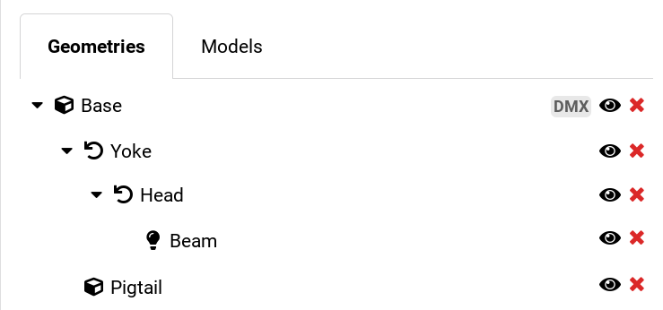
First, indicate the physical placement of connectors on the device. This is done in the Geometry tab of the GDTF Builder by adding a Normal Geometry with a model of primitive type “Pigtail”. The connectors are typically located on the base of the device, so we add it to the Base in our example.
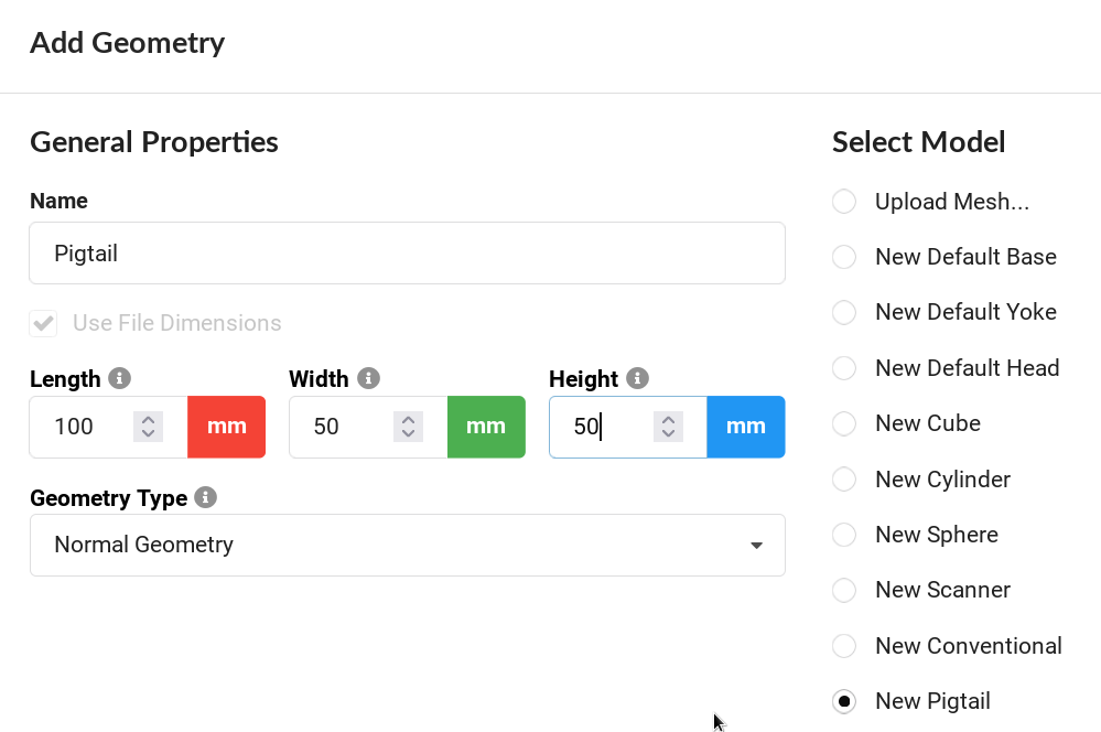
To add the Pigtail:
- Select the Base of the device.
- Click Add Child Geometry.
- Provide a name, for example Pigtail.
- In Select Model, choose New Pigtail.
- Adjust Dimensions.
- Select Geometry Type - Normal Geometry.
- Click OK.
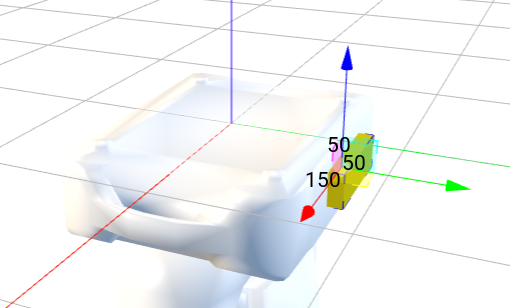
- Adjust X, Y, Z to position the Pigtail to the appropriate location on the Base.
Tip
If the device has more than one panel with connectors, add multiple Pigtails.
For example, linear products with input on one end and output on another end, or a device with inputs on a base and outputs on the yoke or head for an attachable accessory.
Connections on the Pigtail are defined by a Wiring Object for each connector. All Wiring Objects will be children of the Pigtail.
Wiring Object
Wiring Object has the following properties. Not all properties are used in all Wiring Objects.
- Name - user-friendly name to indicate the connection. A good name could include IN for input and OUT for output. Do not use the Connector Type in the name.
- Connector Type - select the connector type or provide a new connector type.
- Component Type - the type of the electrical component used, for example Consumer, PowerSource, Input, Output and so on. Some of these Component Types might extend the list of possible properties of the Wiring Object.
- Signal Type - the type of the signal, for example DMX512, AnalogVideo and so on.
- Pin Count - the number of available pins of the connector type to connect internal wiring to it.
- Signal Layer - indicates connections between Wiring Objects in the device itself. In one device, all Wiring Objects that use the same Signal Layer are connected. A value of 0 connects all Wiring Objects together.
- Orientation - indicates the relative location of this connector on a connection panel.
- WireGroup - name of the group to which this Wiring Object belongs, for example setting WireGroup to “DMX” for all DMX connectors.
Power Input
We start by defining a Powercon True1 Power In connection for our device:
- Select the Pigtail geometry.
- Click Add Child Geometry.
- Provide a name, for example Power IN.
- In Select Model, choose New Empty Geometry.
- Select Geometry Type - Wiring Object.
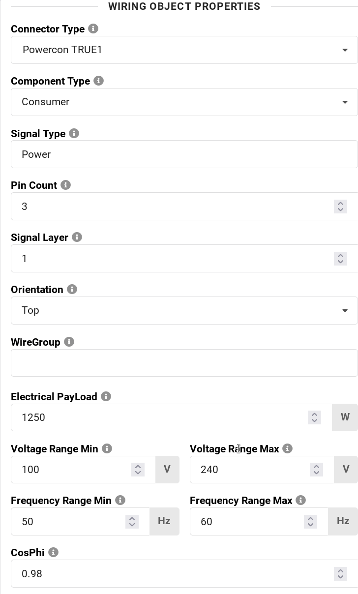
And also fill in the properties of the Wiring Object:
- Connector Type - Powercon True1
- Component Type - Consumer
- Signal Type - Power, or leave empty
- Pin Count - 3
- Signal Layer - 1
- Orientation - Top
- WireGroup - Power or leave empty
- Electrical PayLoad - the electrical consumption in Watts.
- Voltage Range Min - the voltage range minimum value
- Voltage Range Max - the voltage range maximum value
- Frequency Range Min - the frequency range minimum value
- Frequency Range Max - the frequency range maximum value
- CosPhi - the power factor of the device
- Click OK.
Power Output
Our device allows daisy chaining power from one device to another. We continue by defining a Powercon True1 Power Out connection:
- Select the Pigtail geometry.
- Click Add Child Geometry.
- Provide a name, for example Power OUT.
- In Select Model, choose New Empty Geometry.
- Select Geometry Type - Wiring Object.
And also fill in the properties of the Wiring Object:
- Connector Type - Powercon True1
- Component Type - Output
- Signal Type - Power, or leave empty
- Pin Count - 3
- Signal Layer - 1 - this indicates that IN and OUT are connected inside our device
- Orientation - Top
- WireGroup - Power or leave empty
- Click OK.
DMX Connectors
We can continue by adding DMX connectors. These are typically In and Out. We will use NetworkInput and NetworkOutput as the Component Type, and DMX512 as the Signal Type. To indicate that In and Out are connected, assign the same Signal Layer to both DMX connectors. If the device has both 3-pin and 5-pin XLR connectors that are connected to each other, all of them should have the same Signal Layer number.
To add 5-pin XLR DMX In:
- Select the Pigtail geometry.
- Click Add Child Geometry.
- Provide a name, for example DMX IN.
- In Select Model, choose New Empty Geometry.
- Select Geometry Type - Wiring Object.
And also fill in the properties of the Wiring Object:
- Connector Type - 5-pin XLR
- Component Type - NetworkInput
- Signal Type - DMX512
- Pin Count - 5
- Signal Layer - 2
- Orientation - Bottom
- WireGroup - DMX or leave empty
- Click OK.
To add 5-pin XLR DMX Out:
- Select the Pigtail geometry.
- Click Add Child Geometry.
- Provide a name, for example DMX OUT.
- In Select Model, choose New Empty Geometry.
- Select Geometry Type - Wiring Object.
And also fill in the properties of the Wiring Object:
- Connector Type - 5-pin XLR
- Component Type - NetworkOutput
- Signal Type - DMX512
- Pin Count - 5
- Signal Layer - 2
- Orientation - Bottom
- WireGroup - DMX or leave empty
- Click OK.
If the device has 3-pin XLR DMX In and Out, do the same as above, but change the Pin Count to 3. The Signal Layer will be the same if all DMX connectors are connected inside the device.
If the device also has RJ45 network connection, this is how to add it:
- Select the Pigtail geometry.
- Click Add Child Geometry.
- Provide a name, for example Ethernet.
- In Select Model, choose New Empty Geometry.
- Select Geometry Type - Wiring Object.
And also fill in the properties of the Wiring Object:
- Connector Type - 10/100 BaseT Ethernet type
- Component Type - NetworkInOut
- Signal Type - can remain empty, or mention a specific protocol this output is for, for example Video
- Pin Count - 8
- Signal Layer - 3
- Orientation - Left
- WireGroup - can remain empty, especially if there is only one connector of this type
- Click OK.
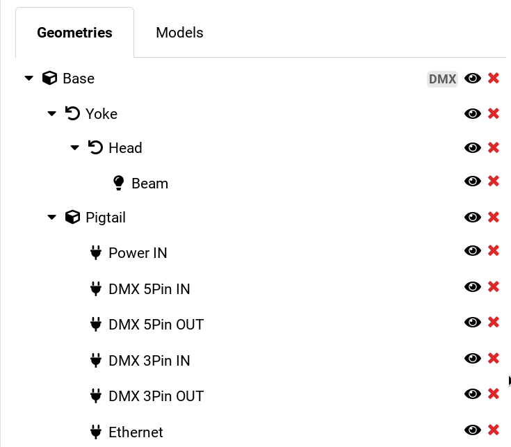
We are done. After adding Power In and Out, DMX 5-pin In and Out, and the Ethernet port, the geometry tree will look like this: