Search the Community
Showing results for tags '3d'.
Found 3 results
-
Could you please provide some guidance on what's the best way to ask manufacturers for the ideal 3D Files to provide all 3 LOD models for a fixture? I would like to have an easy explanation to a CAD engineer so that he can immediately translate the LOD in the table below: The model currently does not have any children. All models of a device combined should not exceed a maximum vertices count of 1200 for the default mesh level of detail. There are three level of details that you can define: Table 33. Mesh level of detail LOD Description Folder 3DS / gltf Low Optional; This is the mesh for fixtures that are far away from the camera. It should have 30% of the the vertexes from the default mesh vertex count. 3ds_low / gltf_low Default This is the default mesh that is used for real time visualization in preprogramming tool. It should have the minimum vertex count possible, while still looking like the fixture in 3D. 3ds / gltf High Optional; This is high quality mesh targeting non-realtime applications, where the vertex count is not that important. There is no limit for the vertex count. 3ds_high / gltf_high Low and High meshes definitions are optional. Place the file with the same name in the defined folder. Sending this table was not always accepted without further questions. For example, the polygon count is also asked back.
-
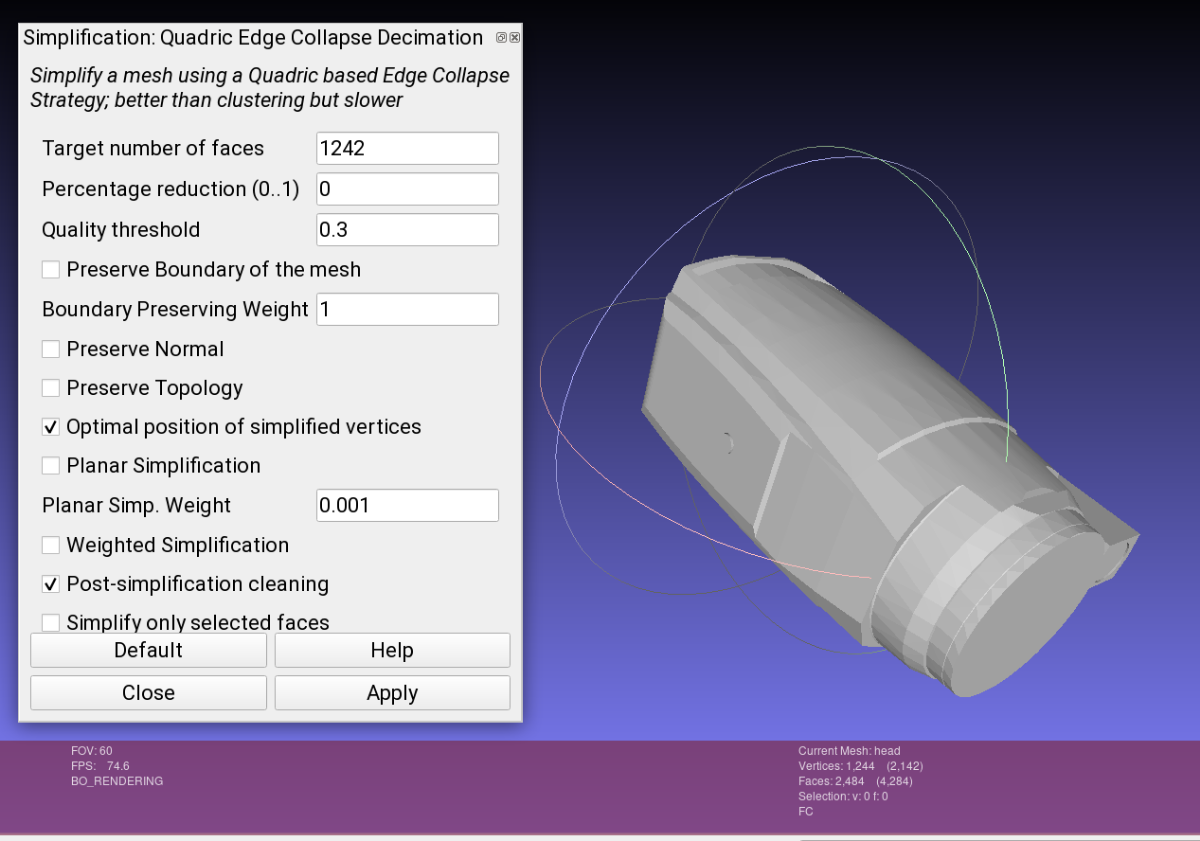
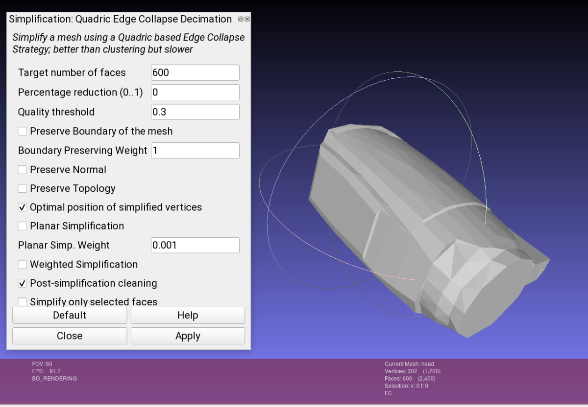
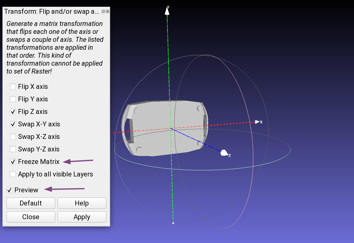
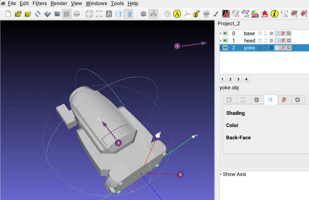
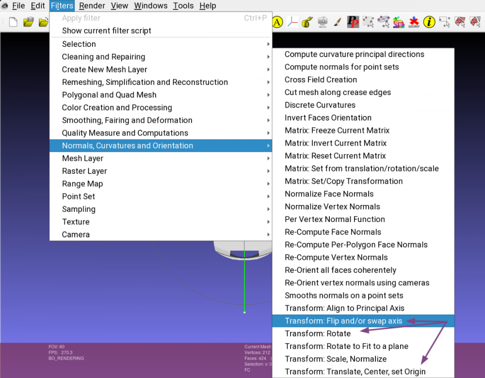
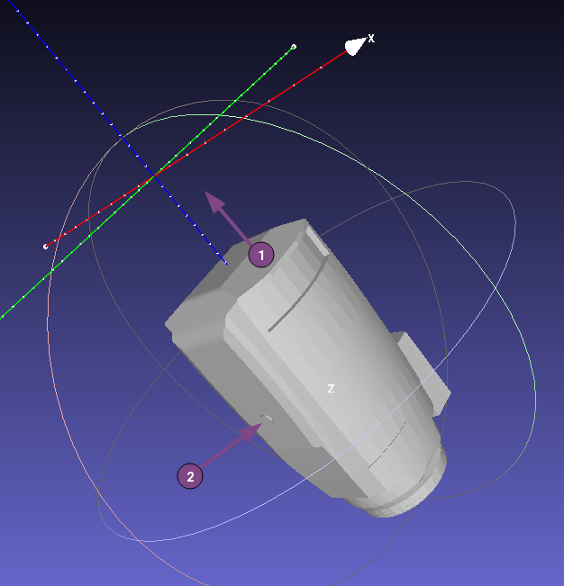
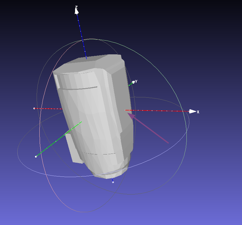
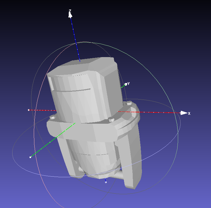
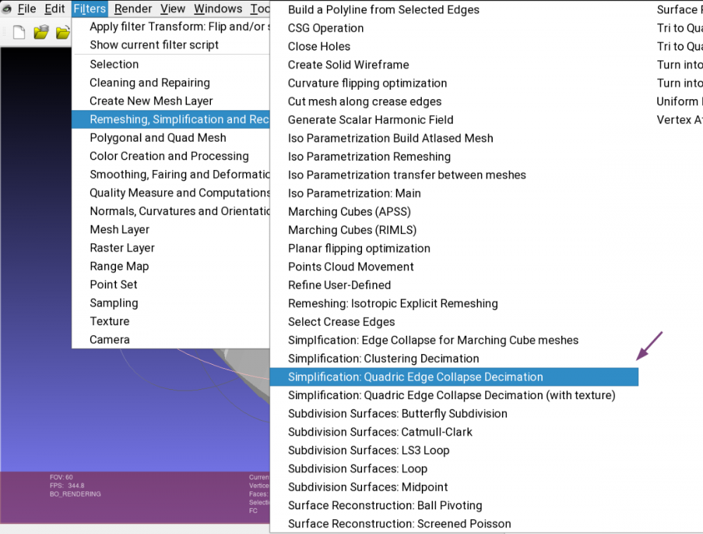
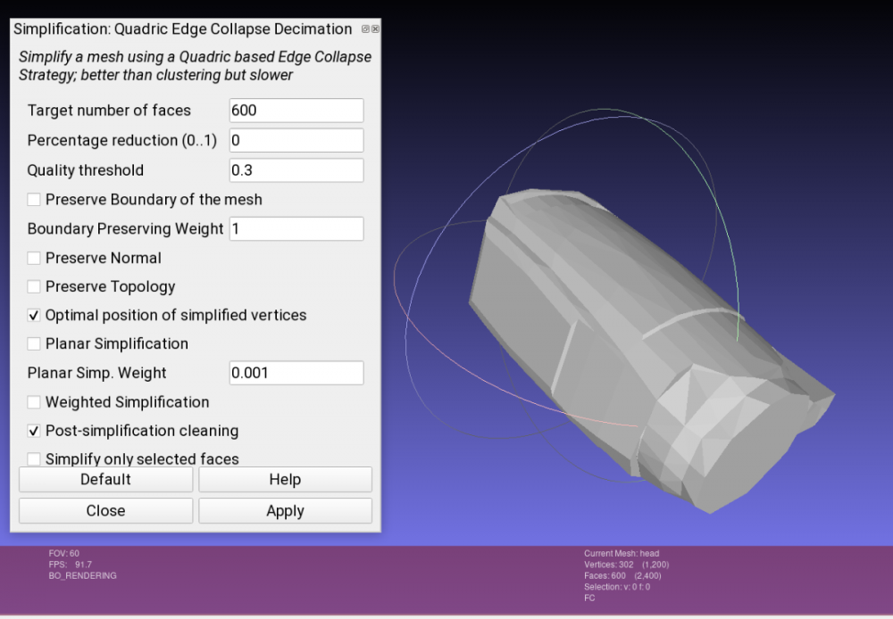
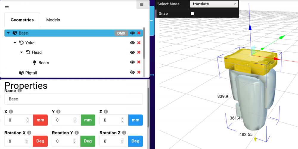
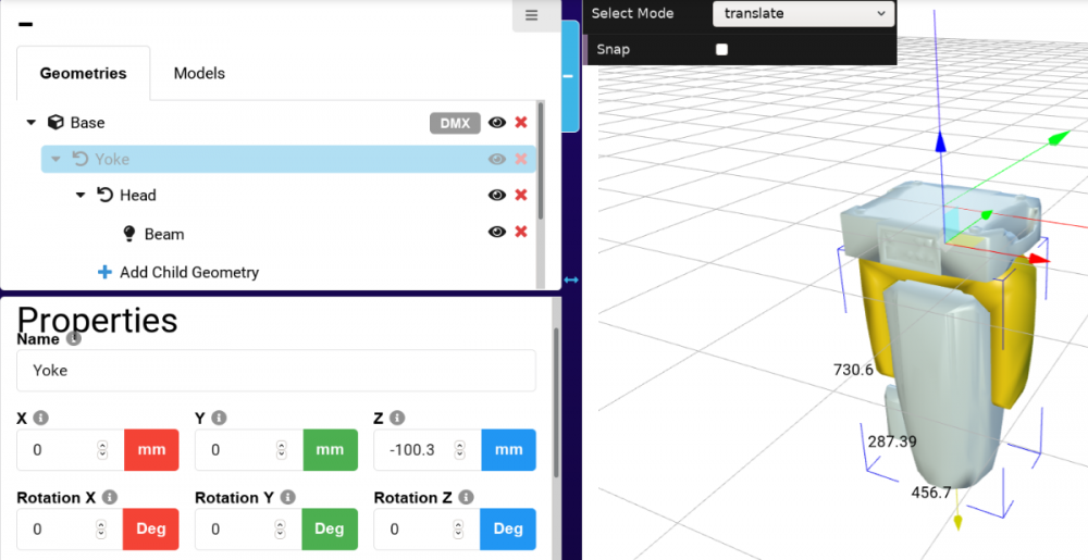
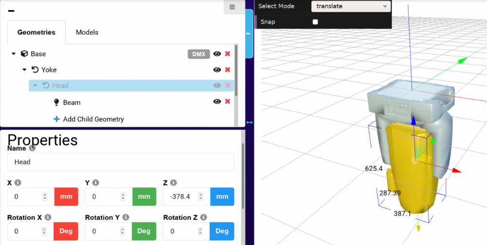
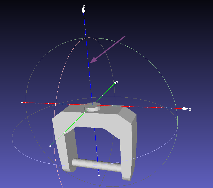
3D models are one of the essential assets in GDTF. Lets see what we need to do to make our 3D files ready for GDTF. You can either use generic 3D models already predefined by GDTF and available in the GDTF builder, or you can provide your models. Models can currently be provided in the form of 3DS files, or in the future it will be also possible to use glTF files. How to create models of the devices is out of scope of this post, what we will look at today is how to modify and adjust existing 3D models provided by the manufacturer for use in GDTF - apply position, rotation, alignment and adjust the quality of the meshes. I like to use Meshlab for assets preparation for GDTF, but you may choose to use other tools, like Blender, Cinema4D or some other software. We will look at a generic moving head fixture with base, yoke and a head. What you usually get from the manufacturer's documentation is a complete 3D drawing, made of individual parts, assembled into the shape of a real fixture. What we need to do for GDTF is to separate each moving part into an individual model and adjust it's origin point and alignment. Here is GDTF definition: The mesh of each fixture part shall be drawn around its own suspension point. The zero point of a device does not necessarily have to contain the offset related to the yoke, but it must be centered on its axis of rotation. The offset is defined by the geometry and has to be related to its parent geometry and not to the base. Which means that in each model's file it's origin point is defining the rotation point. Here is an example of a complete fixture before adjustment, we can see the individual models listed on the side (marked with 1): As you can also see, the origin point (2) is at the center of the base plate, but this is only correct for the base, not for yoke and head, so it will need to be adjusted. Here is another part of the GDTF definition: The device shall be drawn in a hanging position displaying the front view. That results in the pan axis is Z aligned, and the tilt axis is X aligned. 0,0,0 – center base plate. So the device must be drawn upside down, the head must point to negative values of the Z axis and not to the positive direction (3), which means that all models will need to be rotated and adjusted. Your model will most probably be rotated differently, so take this post as a reference. Meshlab allow us to individually select each model and perform operations on it, like Rotations and Positioning (translate) by defining numbers (degrees or digits) of movement. At the same time, it provides a "freeze matrix" feature, which sets the current transformation matrix into the coordinates of the vertices of the mesh (and set this matrix to the identity). In other words, it sets the origin point to the place you need it to be at :), which is what is needed for correct application in GDTF. Here are the Transform tools in the menu. What i like to use instead of multiple rotations is a tool called "Flip and swap axis". One important note: you must always first perform a translation (positioning, to define the origin point - point of the rotation) and the only a rotation, otherwise the rotation would happen along a wrong axis/point. So in my case (your model might be different) we adjust the base by axis flipping and swapping as follows: We can now see that the base bottom plate is facing positive direction of the Z axis, good. Now we need to apply rotation to the yoke and head, because what we have so far looks like this (example of head): The model needs to be positioned (1) and also rotated, so the X axis is defining our rotation (2). You will need precisely measured positions for these offsets, often these will come from manufacturer's drawings or other documentation. Here is the result after applying the Translation and then Rotation in Meshlab: And this is adjusted model of yoke: After we adjust all (base, yoke, head) and If you open all three models together, they will be overlapping each other: This is because the offsets of these models will be defined later, in the GDTF file. For the offsets in GDTF, we will again, need precisely measured values from the device's documentation. Our files are almost ready, but we still must ensure that the models have certain complexity, as for example defining them too detailed (most common case) results in high demand for processing power of the visualizers. You can prepare a detailed, high vertex count file if you perhaps have a demand for a particularly detailed rendering, but for normal operation, you should conform to the GDTF definition: All models of a device combined should not exceed a maximum vertices count of 1200. To ensure this requirement, we must often simplify the model. Meshlab offers it's "Simplification" tool: Before simplification: Simplified, by adjusting the "Target number of faces". See number of vertices at the bottom: Now we can add the models into GDTF in the Builder, here is the result, with corresponding offsets. Here is the base: Yoke: And head: Hope this helps Petr


-
- 1
-

-
- rks
- robe knowledge sharing
- (and 4 more)
-
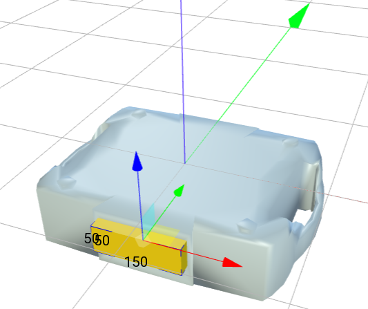
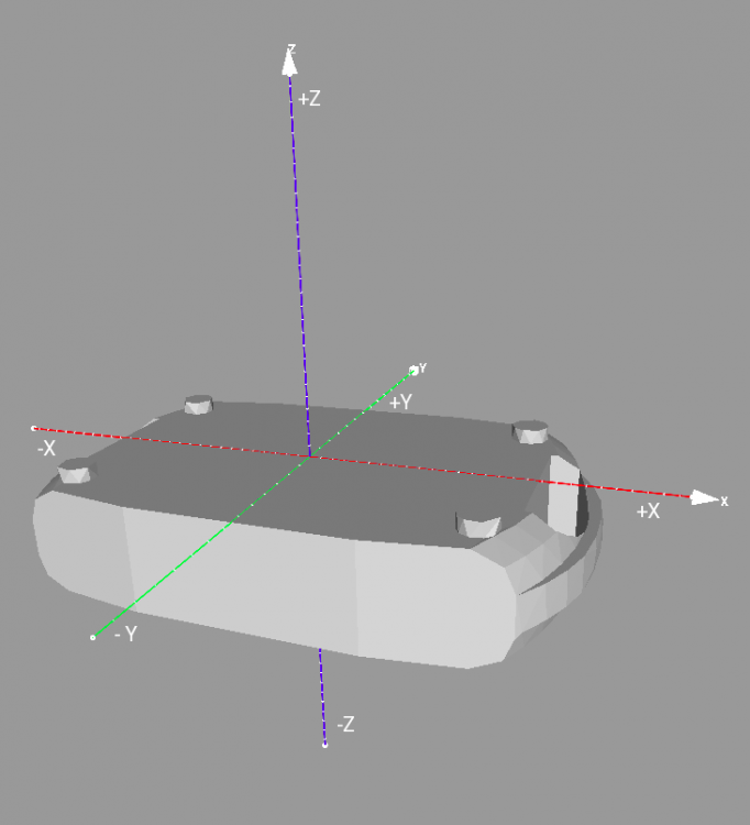
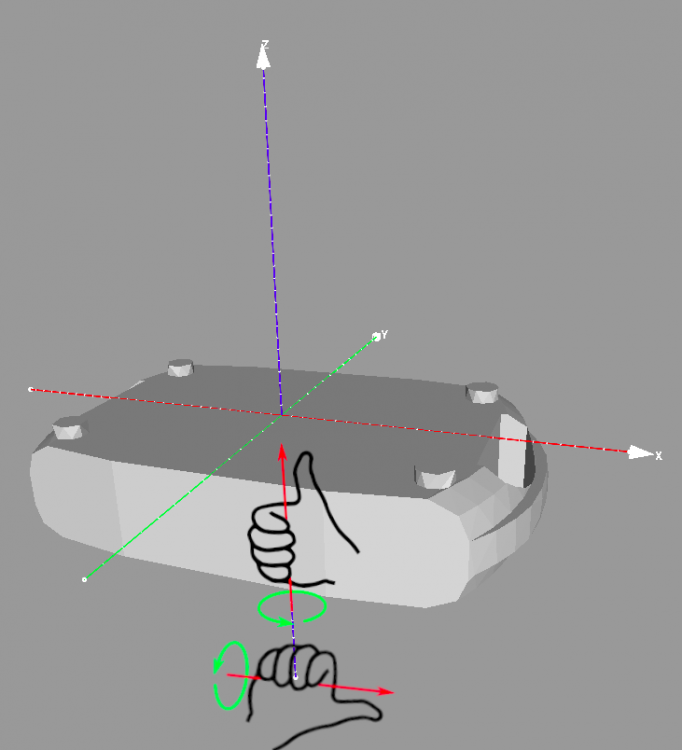
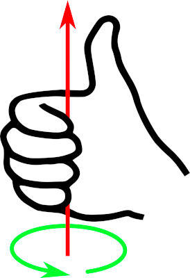
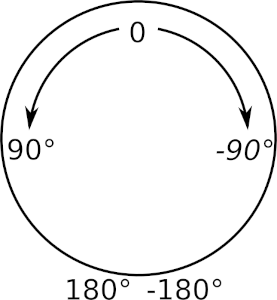
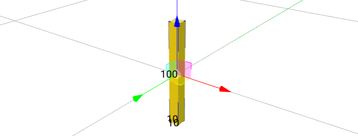
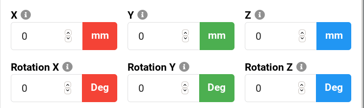
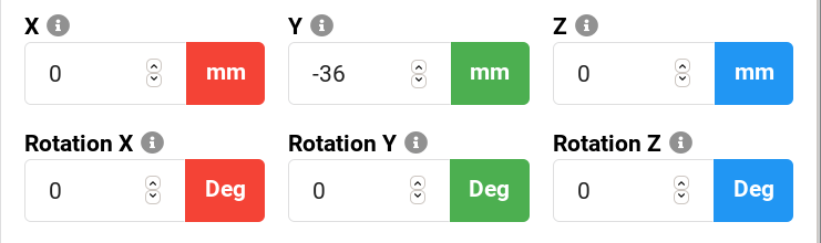
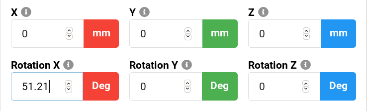
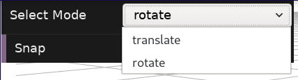
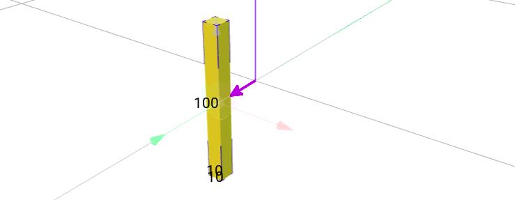
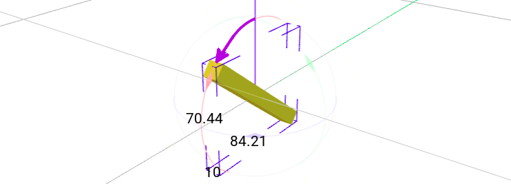
Before you define any physical attributes, you have to make sure to understand how positioning, rotation and orientation is defined in GDTF. 3D space definition GDTF defines this this way: The metric system consists of the Right-handed Cartesian Coordinates XYZ: X – from left (-X) to right (+X), Y – from the outside of the monitor (-Y) to the inside of the monitor (+Y), Z – from bottom (-Z) to top (+Z). For a device, everything starts for you with your 3D model. Here is GDTF definition: The device shall be drawn in a hanging position displaying the front view. That results in the pan axis is Z aligned, and the tilt axis is X aligned. 0,0,0 – center base plate. So this means: the device is upside down the origin point (0,0,0) is in the center of the base plate (meaning, not in the center of the base model, not at the "end" of legs) you draw the device with it's front in the direction of the -Y axis (facing you in the builder) by placing the "pigtail" model, you indicate the location of the panel with connectors or the power cord the positioning and orientation is how it must be done in the 3D model, especially for the base, because the top geometry (often the base) cannot contain any extra defined position (offsets) and/or rotations If you for example decide that the "front of your device" is where the connector panel is, this would be the result: Rotation Here is GDTF definition: The metric system consists of the Right-handed Cartesian Coordinates XYZ. Let me re-phrase this as this is basically the right handed rule: The right thumb points along the Z axis in the positive direction. Positive rotation is shown by fingers curled in the direction of rotation. When viewed from the top or Z axis the system is counter-clockwise. The top here is you, naturally looking at your hand: The counter-clockwise sounds strange, but because in real life you often "observe" it from the bottom, you consider this "normal" for screw threads and so on, because to screw them in, you turn them to the right. This is how it looks applied to the model/geometry, indicating pan/tilt: So when viewed from the top: Positive values are increasing values, so angles from 0° to 360°, from -360° to 0° of from -360° to 360° are positive, angles from 0° to -360°, from 360° to 0° or from 360° to -360° are negative. When defining angular ranges, you typically start from center (0°) and define - and + ranges. Based on this, you can determine how to correctly fill values for pan/tilt angular ranges, gobo rotations and so on. In the builder You can also use the Builder to show you the positioning (translate) and rotation (rotate), you can choose a mode to manipulate the model: Centered: Model: Displayed values: Moved "to the front", to negative values on Y axis: Model: Displayed values: Rotated "in positive (CCW)" direction: Model: Displayed values: Hope this helps Petr