Search the Community
Showing results for tags 'orientation'.
Found 1 result
-
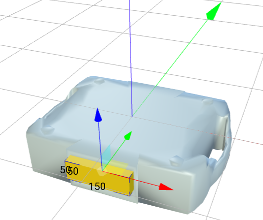
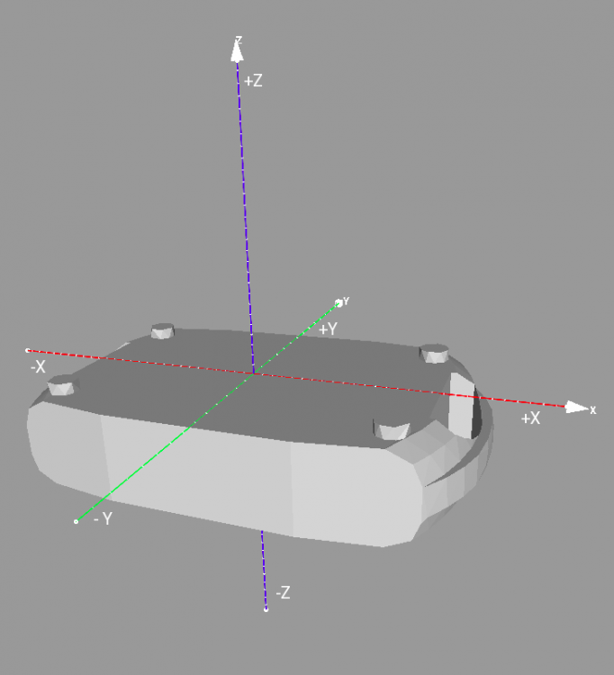
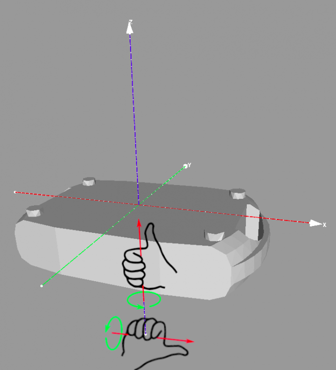
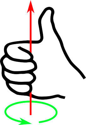
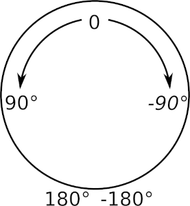
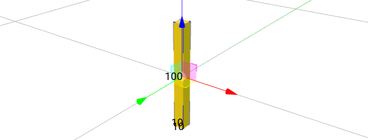
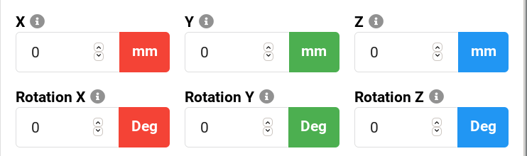
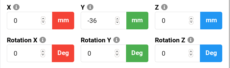
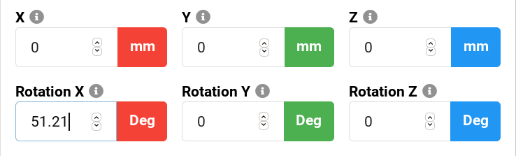
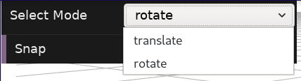
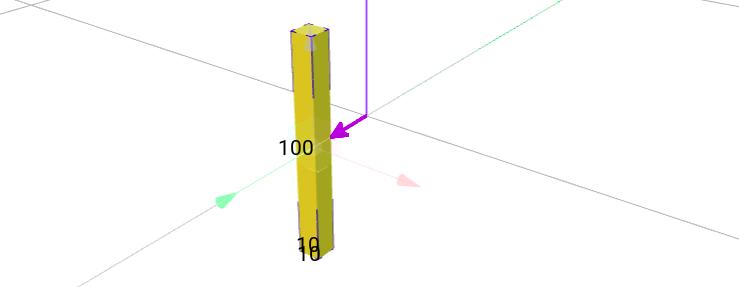
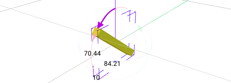
Before you define any physical attributes, you have to make sure to understand how positioning, rotation and orientation is defined in GDTF. 3D space definition GDTF defines this this way: The metric system consists of the Right-handed Cartesian Coordinates XYZ: X – from left (-X) to right (+X), Y – from the outside of the monitor (-Y) to the inside of the monitor (+Y), Z – from bottom (-Z) to top (+Z). For a device, everything starts for you with your 3D model. Here is GDTF definition: The device shall be drawn in a hanging position displaying the front view. That results in the pan axis is Z aligned, and the tilt axis is X aligned. 0,0,0 – center base plate. So this means: the device is upside down the origin point (0,0,0) is in the center of the base plate (meaning, not in the center of the base model, not at the "end" of legs) you draw the device with it's front in the direction of the -Y axis (facing you in the builder) by placing the "pigtail" model, you indicate the location of the panel with connectors or the power cord the positioning and orientation is how it must be done in the 3D model, especially for the base, because the top geometry (often the base) cannot contain any extra defined position (offsets) and/or rotations If you for example decide that the "front of your device" is where the connector panel is, this would be the result: Rotation Here is GDTF definition: The metric system consists of the Right-handed Cartesian Coordinates XYZ. Let me re-phrase this as this is basically the right handed rule: The right thumb points along the Z axis in the positive direction. Positive rotation is shown by fingers curled in the direction of rotation. When viewed from the top or Z axis the system is counter-clockwise. The top here is you, naturally looking at your hand: The counter-clockwise sounds strange, but because in real life you often "observe" it from the bottom, you consider this "normal" for screw threads and so on, because to screw them in, you turn them to the right. This is how it looks applied to the model/geometry, indicating pan/tilt: So when viewed from the top: Positive values are increasing values, so angles from 0° to 360°, from -360° to 0° of from -360° to 360° are positive, angles from 0° to -360°, from 360° to 0° or from 360° to -360° are negative. When defining angular ranges, you typically start from center (0°) and define - and + ranges. Based on this, you can determine how to correctly fill values for pan/tilt angular ranges, gobo rotations and so on. In the builder You can also use the Builder to show you the positioning (translate) and rotation (rotate), you can choose a mode to manipulate the model: Centered: Model: Displayed values: Moved "to the front", to negative values on Y axis: Model: Displayed values: Rotated "in positive (CCW)" direction: Model: Displayed values: Hope this helps Petr