Search the Community
Showing results for tags 'rks'.
Found 15 results
-
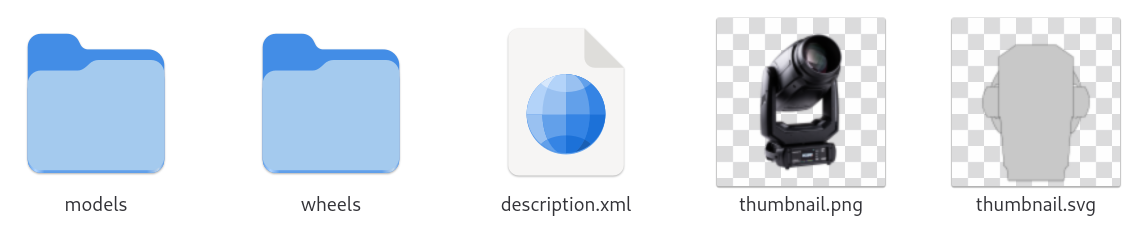
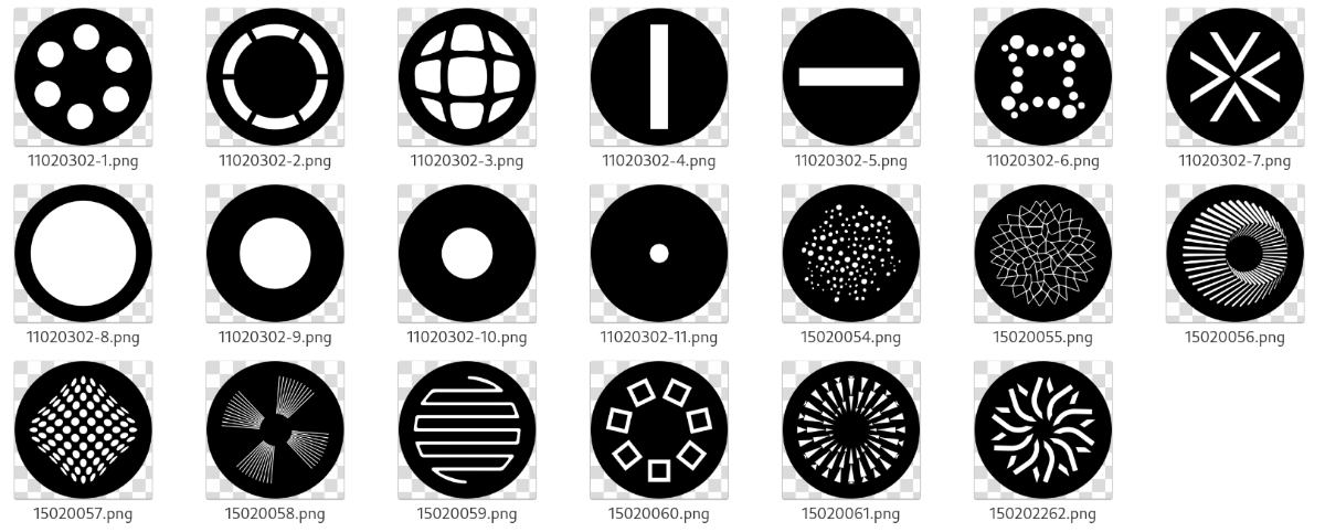
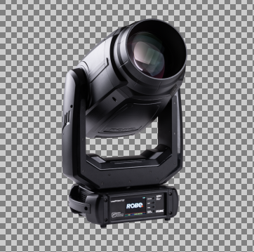
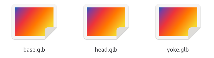
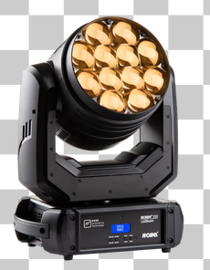
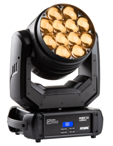
Extracting resource files directly from GDTF Sometimes it may be useful to extract some data like gobo images, 3D models, or other files directly from the GDTF file. This is possible, because every GDTF file is a zip archive with .gdtf extension. To access the content of GDTF, rename the file from .gdtf to .zip and then open as any other zip archive. When you unpack the .gdtf file, this is what you can typically see: The description.xml file contains the description of the device type. There is a lot of information in this file and it requires deeper understanding of the GDTF Specification to utilize it: The thumbnail.png provides an image of the product: The thumbnail.svg is providing a 2D symbol for planning tools: As these are normal .png and .svg files, they can be copied and used directly in any supportive application as needed. The wheels folder contains all the images for gobos, animation wheels and so on: The naming of the files is up to the GDTF creator, while the details of the image are as far as format, resolution, color conventions and so on. The models folder contains subfolders for 3D and 2D models, for a better structural overview: ./models/3ds ./models/gltf ./models/svg The existence of these folders is optional and depends on presence of files specific to these folders. If the GDTF file does not contain any .3ds files, then the folder ./models/3ds will typically not exist. If the GDTF files contains 3D models in gltf format, then they will be in folder ./models/gltf, the content of the folder then may look like this: These .glb files can be used in applications utilizing 3D files. The positioning and offsets of these 3D files has been previously explained in several other RKS articles and is also defined in the GDTF Specification, together with more information on the possibility to define also 2D models, 3D models in higher or lower level of details and so on. For the most time, extracting 3D models and gobo images in what is needed. For the examples above, we used the the Robe Robin LedPOINTE, which is available in the GDTF Share here. Hope this helps, Petr


-
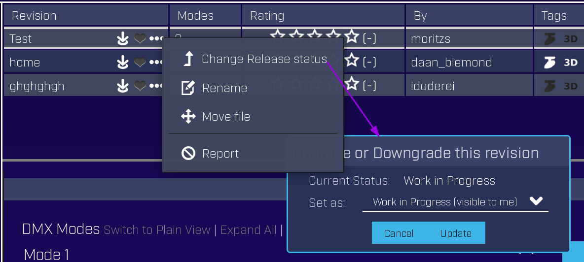
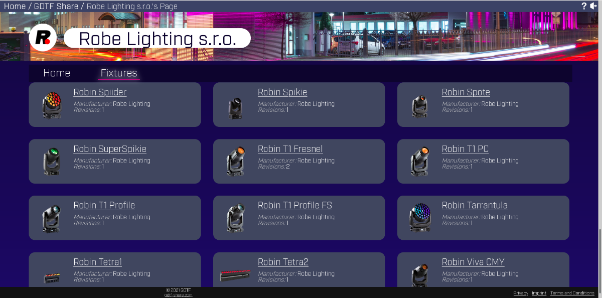
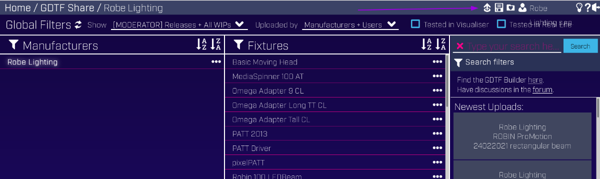
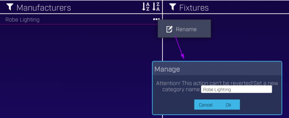
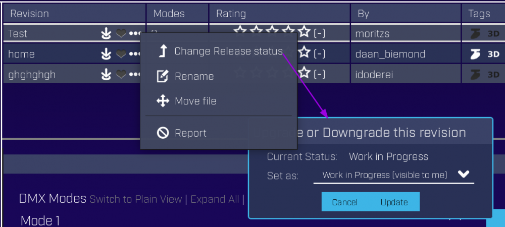
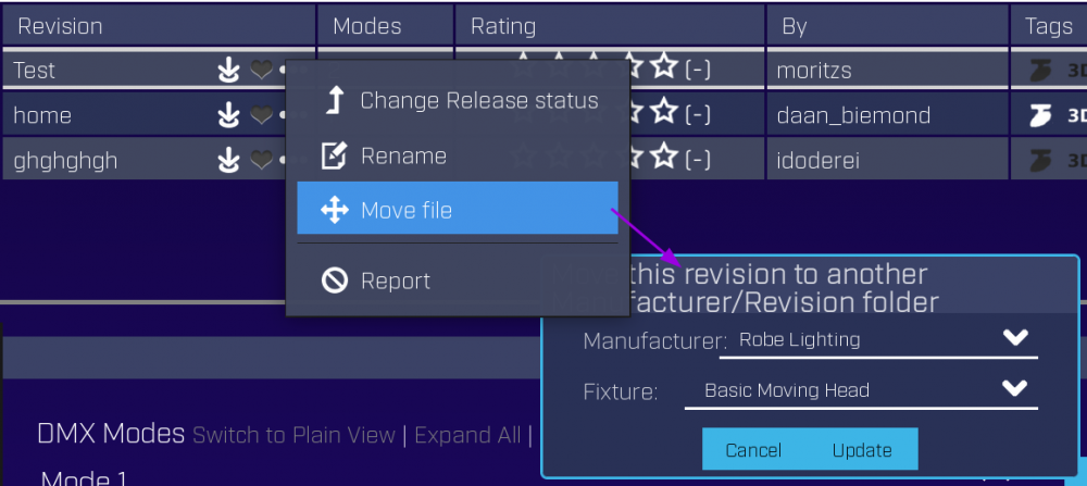
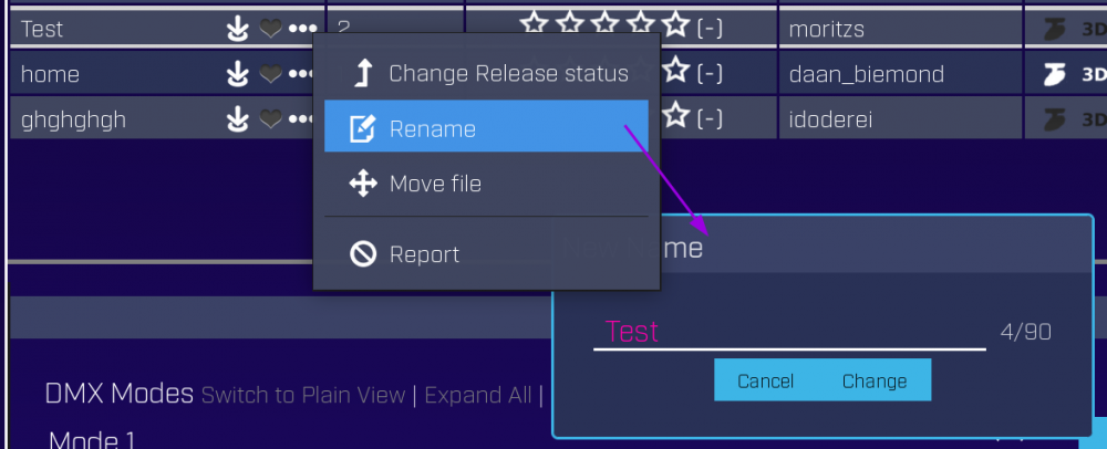
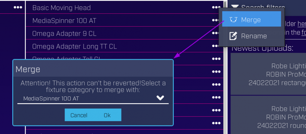
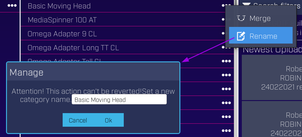
Manufacturer moderation Manufacturers have special power that allows them to manage "their" manufacturer folder/category to keep it organized. To use their "moderator" tools, there is a "Moderator" in the "Show" filter: This allows manufacturers to rename the name of their folder. This is why Robe folder is called "Robe Lighting" while the name of our company is "Robe lighting s.r.o.": Moderating operations can be done on device "subfolders" or on individual files - folders can be merged and renamed: Individual files can be also moved around or have their Revisions renamed: Individual files can also be set to hidden for public by setting their status to WIP (work in progress): Manufacturer's pages Each manufacturer also has a dedicated page with a representative listing of the files for their devices, here is what it looks like: Hope this helps Petr


-
- 1
-

-
- rks
- robe knowledge sharing
- (and 2 more)
-
For device manufacturers who provide or would like to provide GDTF files for their devices, we provide extra features in the GDTF Share and in the GDTF Builder, like brand category management, manufacturer landing page or download only (no upload to GDTF Share) option in the GDTF Builder. There is a dedicated section in the forum and also a monthly manufacturers meeting about GDTF and MVR. Account registration If you are a device manufacturer, your first step would be to register a free account in the GDTF Share (https://gdtf-share.com/). Then continue and register in the GDTF Forum (https://gdtf-share.com/forum/) with the same email. Often companies use info@... or gdtf@... email, to have company wide address not linked to a single individual. Make sure to use an email from a domain which clearly asserts connection with the brand. Get in touch After creating the account, use the Contact us page and let us know the email address you used in the GDTF Share and in the Forum, so we can mark your account as a manufacturer. This will give you the possibility to manage your manufacturer brand in the GDTF Share and will provide you with special access in the GDTF Forum, which is the place to ask further questions about GDTF. Once you let us know the email used for registration, we will also add your email to our list of manufacturers who receive an invite to the monthly GDTF/MVR manufacturers meeting, where we discuss progress, proposals and questions. Past meeting notes and meeting recordings are available in the GDTF Share Forum, in a dedicated, Manufacturers only accessible section area, link here. Enable manufacturer page As for being listed on the GDTF website in the Manufacturers section, make sure to enable your Manufacturer page in the GDTF Share in the Edit Profile of your account. This page is useful for manufacturers providing GDTF files, as well as for software vendors who utilize GDTF and MVR in their software. Customize the page with your company logo and header image, we can then use this image for listing on the GDTF Share page. The header image of 4096px x 768px should be a good size to fit most situations. You can add posts, describing your product and the support for GDTF/MVR it provides. The page also provides listing of your GDTF files which you can share with your customers, see this example page. Information about GDTF Share moderation tools for manufacturers: To create GDTF files, the GDTF Builder application is used (https://fixturebuilder.gdtf-share.com/). To learn about the GDTF Specification, GDTF Share, GDTF Builder and more, please see the Documentation resources post:


-
Documentation Resources for GDTF Introduction Start by registering a free account on the GDTF Share, this allows you to use the GDTF Fixture builder and also to join this GDTF Forum and ask questions. GDTF Builder GDTF files are created in the free to use GDTF Fixture builder - a web based editor to create and modify GDTF files. There are several documentation resources for the GDTF Builder: How to Create a GDTF Lighting Fixture YouTube video series from 2024. Introduction to the GDTF Builder YouTube video series. GDTF Builder manual describes creation of a GDTF file from start to the end. How to articles, describing dedicated topics in more detail, for example Wheels, Virtual channels or Prisms. Robe Knowledge Sharing (RKS) articles on the GDTF forum, describe particular domain knowledge to depth, for example basics on 3D positioning, orientation and rotations or 3D geometry preparations. GDTF Share The GDTF Share is a platform for the exchange of GDTF files. It provides a central repository, connected with a GDTF file editor, for upload, search and download of GDTF files, with powerful filtering and management system for users and GDTF files creators. GDTF Share manual - explains how to create a free account, how to navigate the GDTF Share and how to upload, manage and download GDTF files. How to Create an Account for the GDTF Builder and GDTF Share Tutorial YouTube video series. Other resources for the GDTF Specification The GDTF Specification is the text of the DIN SPEC 15800:2022-02 also known as GDTF Version 1.2. GDTF Spec documentation on this server. GDTF & MVR Specification working repository on GitHub GDTF Forum - ask questions about GDTF & MVR here FAQ - answers for questions frequently asked by manufacturers and entertainment professionals
-
One of the often raised questions about GDTF is "which data is required to be included inside GDTF files". This can be dependent on the use-case for the file and it is always subjective, but here we try to summarize the issue to provide a hierarchical approach to understanding user needs. GDTF Data expectation per use-case: Use case → Control Planning Previz Rendering Feature ↓ Fixture name essential essential essential essential Manufacturer essential essential essential essential RDM complementary Description complementary essential essential essential Product image complementary essential essential essential 2D thumbnail complementary essential complementary complementary Operating temperatures complementary Weight essential Leg height essential complementary complementary 3D model template essential essential essential essential 3D model real fixture complementary complementary complementary essential 3D model PBR workflow peripheral Beam model basic shape essential essential Beam model real world complementary complementary 2D model symbols complementary Gobo images essential complementary complementary essential Prism slots complementary complementary essential Color slots essential complementary essential Animation wheels complementary complementary essential Virtual channels (dimmers, tilt…) essential Channel dependencies complementary DMX (control) description essential essential essential DMX Macros complementary Beam data complementary complementary essential Colors (emitters, filters) complementary complementary essential Movement speeds complementary complementary essential Movement acceleration complementary complementary essential Movement ranges essential complementary complementary Movement directions essential complementary complementary DMX profiles (curves) complementary complementary complementary Subphysical properties peripheral Wiring object data (Power usage...) complementary GDTF Data expectation combined: Essential Nice to have Like to have Basic metadata Fixture name Manufacturer RDM Description Product image 2D thumbnail Operating temperatures Weight Symbols Leg height 3D model template 3D model real fixture 3D model PBR workflow Beam model basic shape Beam model real world 2D model symbols Media Gobo images Prism slots Color slots Animation wheels Control Virtual channels (dimmers, tilt…) Channel dependencies DMX (control) description DMX Macros Physical measurements Beam data Colors (emitters, filters) Movement speeds Movement acceleration Movement ranges Movement directions DMX profiles (curves) Subphysical properties Wiring object data (Power usage...)
-
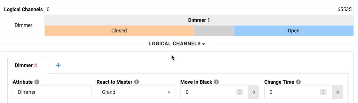
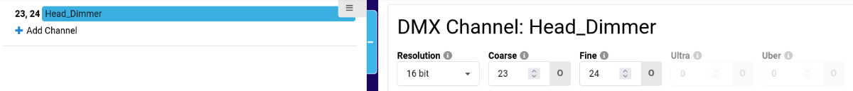
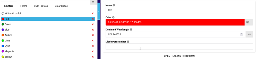
Here is a list of frequent errors we can see some new GDTF authors are making, together with description on how to eliminate these issues. By following this advice you will be creating GDTF files of much better quality. Custom GDTF Attributes Do not define custom attributes. If you think that the attribute you are needing is not in the GDTF Builder, look more closely. In 99%, the needed attribute is already defined in GDTF and thus it allows all software utilizing GDTF to know which real world behavior is described by that GDTF attribute. If unsure about creating a new attribute, ask in the forum, especially if you want to be sure that your GDTF file is correct. Here are some commonly missed GDTF attributes: Dimmer, which is controlling intensity of the device. Do not create an attribute "Intensity". Colors. Do not create "Red" of "Green". These already exist as for example ColorAdd_R, ColorAdd_G, ColorAdd_B for direct color mixing, ColorRGB_Red, ColorRGB_Green, ColorRGB_Blue for indirect color mixing, ColorSub_C, ColorSub_M, ColorSub_Y for Cyan, Magenta, Yellow subtractive color mixing. You can view the list of all GDTF attributes with extended description for each item here. Coarse and Fine Channels When defining a DMX Channel, you can choose a Resolution of the channel. This then allows you to assign a DMX offset for Coarse and Fine, as per image below. Do not create channels "Dimmer Fine" or "Red Fine" channels. Emitters/Filters Only define a color Emitter or a Filter if you have measurements of the colors. Do not define Emitters/Filters to just click some random R, G, B values. 3D Models Ideally, use a real 3D model of the device. If you do not have a 3D model of the fixture, you can use the default head, yoke, base models provided by the GDTF Builder, if these default models look like the real device you are describing. If the default head, yoke, base models do not describe your device correctly, it is often better to use the predefined cube or cylinder as a model. Do not use for example the default base instead of a generic cube, it will look very ugly. Beam Geometry For beam geometry, typically use a cylinder with a small height. Do not use randomly some other predefined models like the head or base. Hope this helps. If unsure, just ask here in the forum. Petr


-
Defining Wiring Connections for Electrical Devices To describe connectors and other connection details of attaching of electrical devices that can be wired, dedicated type of Geometry called Wiring Object is used. All specified parameters and details of the Wiring Object are defined in Geometry Type Wiring Object in the GDTF Spec. In this example, we define connectors for a device which has a Power (Power In and Power Out via Neutrik Powercon True1), DMX (DMX In and DMX Out via XLR 5Pin) and a Network (RJ45 connector). Pigtail First we need to indicate physical placement of connectors on the device. This is done in the Geometry tab of the GDTF Builder by adding a Normal Geometry with a model of primitive type "Pigtail". The connectors are typically physically located on the base of the device, so we add it to the Base in our example. To add the Pigtail: select the Base of the device click Add Child Geometry give it a name Pigtail in the Select Model choose New Pigtail adjust Dimensions select Geometry Type - Normal Geometry click OK adjust X, Y, Z to position the Pigtail to the appropriate location on the Base Adding Pigtail screen Pigtail is a child of the Base Pigtail positioned to indicate real location of connectors on the device If the device has more than one panel with connectors, add multiple Pigtails. For example linear products with Input on one end and Output on another end, or a device with Inputs on a base and Outputs on the yoke or head for some attachable accessory. Connections on the Pigtail are defined by Wiring Object geometry for each connector. All these Wiring Object geometries will be children of the Pigtail. Wiring Object geometry has the following properties. Not all the following properties are used in all Wiring Objects. Name - user friendly name to indicate the connection. Good name could include IN for input, OUT for output. Do not use the Connector Type in the name. Connector Type - select the type of used connector or provide new connector type. Component Type - the type of the electrical component used, for example Consumer, PowerSource, Input, Output and so on. Some of these Component Types might extend the list of possible properties of the Wiring Object. Signal Type - the type of the signal, for example DMX512, AnalogVideo and so on Pin Count - the number of available pins of the connector type to connect internal wiring to it Signal Layer - this indicates connection between Wiring Objects in the device itself. In one device, all Wiring Geometries that use the same Signal Layer are connected. Special value is 0, which is connecting all Wiring Geometries together. Orientation - indicates relative location of this connector on a connection panel WireGroup - name of the group to which this wiring object belongs to, for grouping all DMX connectors together by setting the WireGroup to "DMX" for all DMX connectors. Power Input We start by defining Powercon True1 Power Input connection for our device: Select Pigtail geometry click Add Child Geometry give it a name Power IN in the Select Model choose New Empty Geometry select Geometry Type - Wiring Object And also fill in the properties of the Wiring Object: Connector Type - Powercon True1 Component Type - Consumer Signal Type - Power, or leave empty Pin Count - 3 Signal Layer - 1 Orientation - Top WireGroup - Power or leave empty Electrical PayLoad - the electrical consumption in Watts. Voltage Range Min - the voltage range's minimum value Voltage Range Max - the voltage range's maximum value Frequency Range Min - the Frequency range's minimum value Frequency Range Max - the Frequency range's maximum value CosPhi - The Power Factor of the device click OK Properties of Power IN Wiring Object Power Output Our device allows daisy chaining power from one device to another. We continue by defining Powercon True1 Power Output connection: Select Pigtail geometry click Add Child Geometry give it a name Power OUT in the Select Model choose New Empty Geometry select Geometry Type - Wiring Object And also fill in the properties of the Wiring Object: Connector Type - Powercon True1 Component Type - Output Signal Type - Power, or leave empty Pin Count - 3 Signal Layer - 1 - this indicates that IN and OUT are connected inside our device Orientation - Top WireGroup - Power or leave empty click OK DMX Connectors We can continue by adding DMX connectors. These are typically In and Out, we will use NetworkInput and NetworkOutput as a Component Type, the Signal Type will be DMX512. To indicate that In and Out are connected, we will assign same Signal Layer to both DMX connectors. In case that there are both 3Pin and 5Pin XLR connectors on the device which are typically all connected to each other, all of them will have the same Signal Layer number. To add 5 Pin XLR DMX In: Select Pigtail geometry click Add Child Geometry give it a name DMX IN in the Select Model choose New Empty Geometry select Geometry Type - Wiring Object And also fill in the properties of the Wiring Object: Connector Type - 5-pin XLR Component Type - NetworkInput Signal Type - DMX512 Pin Count - 5 Signal Layer - 2 Orientation - Bottom WireGroup - DMX or leave empty click OK To add 5 Pin XLR DMX Out: Select Pigtail geometry click Add Child Geometry give it a name DMX OUT in the Select Model choose New Empty Geometry select Geometry Type - Wiring Object And also fill in the properties of the Wiring Object: Connector Type - 5-pin XLR Component Type - NetworkOutput Signal Type - DMX512 Pin Count - 5 Signal Layer - 2 Orientation - Bottom WireGroup - DMX or leave empty click OK If the device has also 3 Pin XLR DMX Input and Output, do the same as above, just change the Pin Count to 3. The Signal Layer will be the same if all DMX connectors are connected inside the device. If the device also has RJ45 network connection, this is how to add it: Select Pigtail geometry click Add Child Geometry give it a name Ethernet in the Select Model choose New Empty Geometry select Geometry Type - Wiring Object And also fill in the properties of the Wiring Object: Connector Type - 10/100 BaseT ethernet type Component Type - NetworkInOut Signal Type - can remain empty or mention a specific protocol this output is for, for example Video Pin Count - 8 Signal Layer - 3 Orientation - Left WireGroup - can remain empty, especially if there is only one connector of this type click OK We are done. After adding Power In and Out, DMX 5 pin In and Out and also Ethernet port, this is what the geometry tree will look like: Pigtail with connectors Hope this helps Petr See all Robe Knowledge Sharing Articles.
-
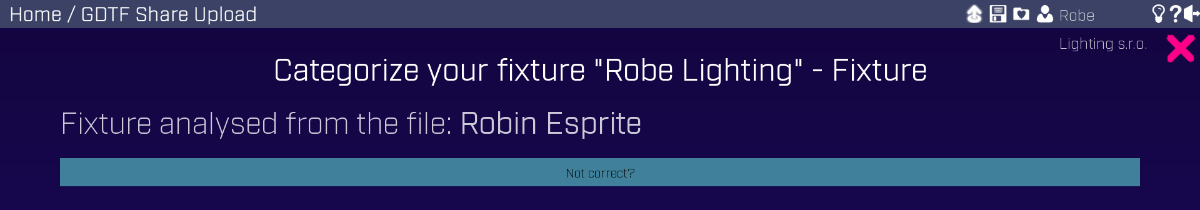
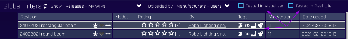
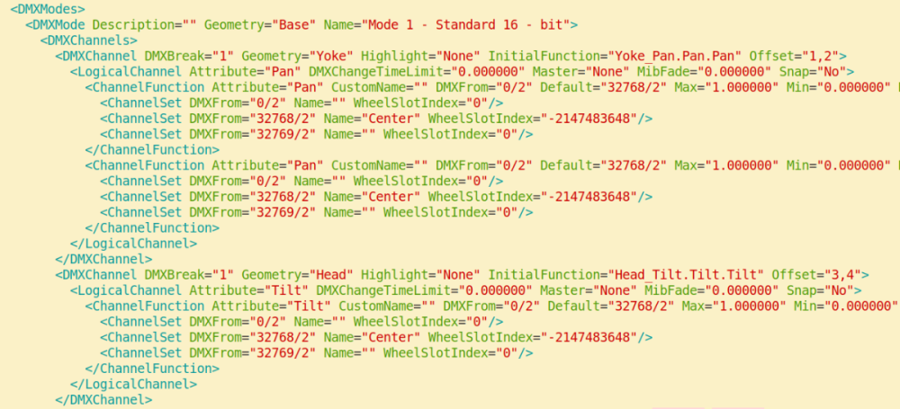
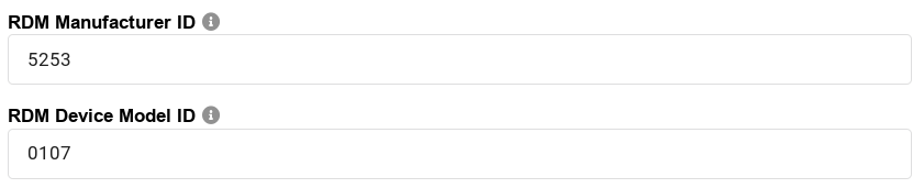
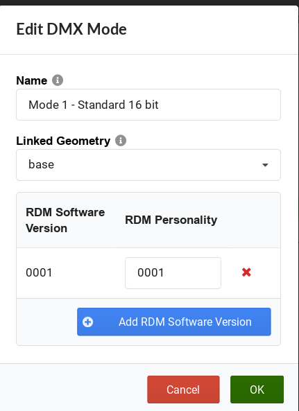
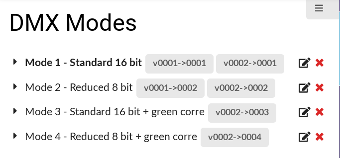
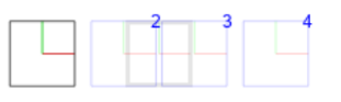
A DMX Mode is a container holding definition of DMX channels and GDTF allows us to define multiple DMX modes for a single device withing one GDTF file. The concept of multiple DMX modes is good, because not only we can have a complete device definition in a single GDTF file, but we can also define DMX modes for different software version of the device. This allows us to provide both older and newer versions of DMX definitions if needed. For this to work in the GDTF Builder, we must first define RDM details on the Fixture tab: If you do not know the Manufacturer ID, it can be found here: https://tsp.esta.org/tsp/working_groups/CP/mfctrIDs.php . The Device Model must be retrieved from manufacturer documentation, or you can also try to find it in the OpenLighting database: http://rdm.openlighting.org/model/display?manufacturer=21075&model=263 . Do note that you fill in the hexadecimal values, not the decimal representation. With these data being filled in, you can now define DMX Model and provide the name, top level geometry (base) and the "RDM Software version + RDM Personality ID" pair for each DMX Mode: If you have for example a DMX Mode, which was added only in software version 2, you can define this pair of Software Version - Personality values in the DMX Mode definition. So in the following example, we have a DMX Mode 1 and 2 available in software versions 1 and 2. Then we have DMX Modes 3 and 4, which were only added on software version 2: Hope this helps, Petr
- 4 replies
-
- 1
-
-
- rks
- robe knowledge sharing
- (and 2 more)
-
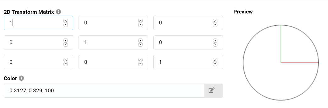
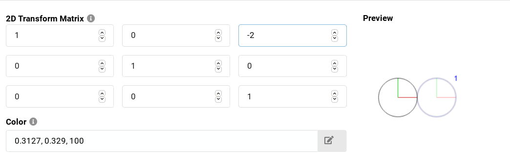
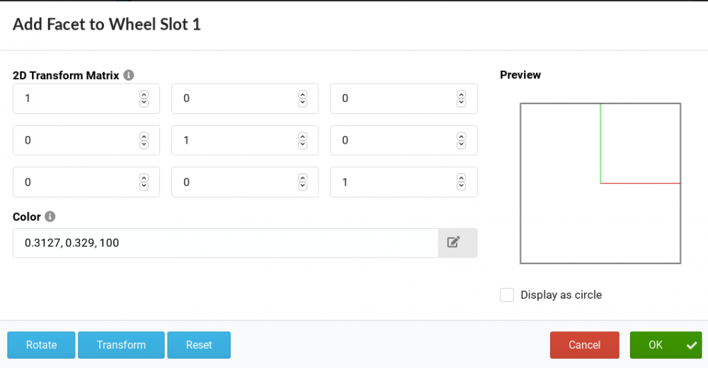
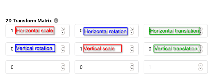
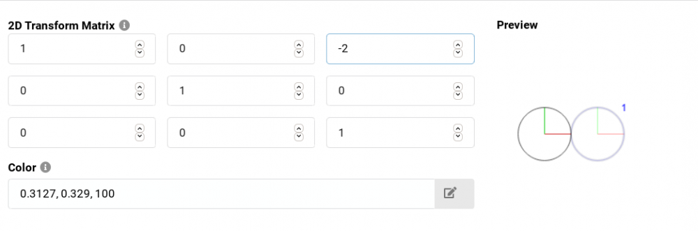
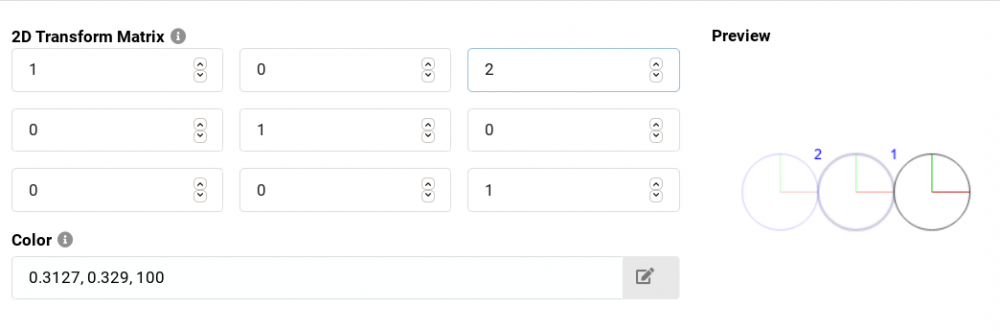
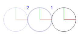
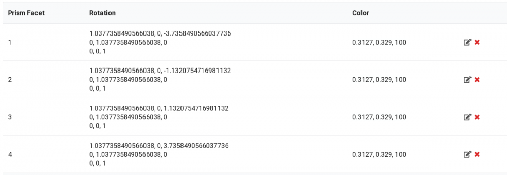
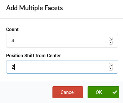
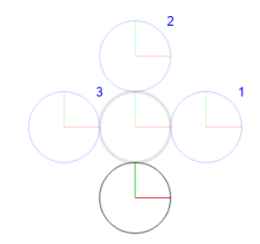
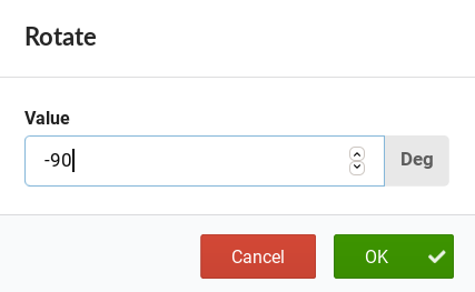
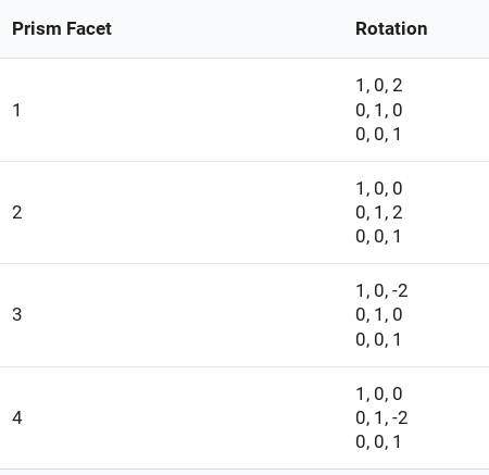
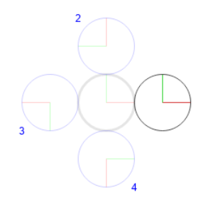
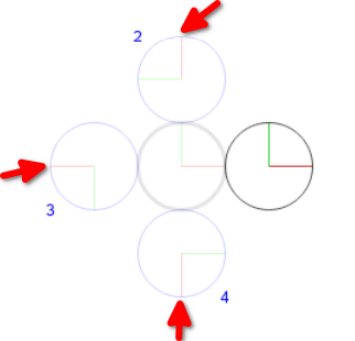
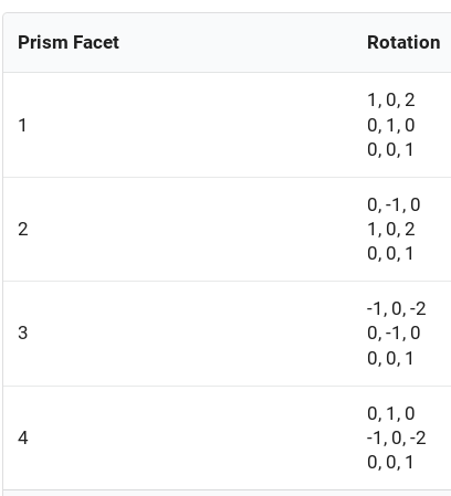
Prisms in GDTG are part of the Wheel and in particular, they are inside of what is called a Wheel Slot. Prisms definitions in GDTF allow precise definition of each of the prism facet and it is done by using transformations represented by Rotation matrices. There are many resources on rotation matrixes, for example this Wikipedia article and also many game engine related tutorials and articles, like this one, which is useful for our 2D prism definitions. In the GDTF Builder, there is a really nice Prism editor which can do some of the math for you, like rotations and transformation (movement): The editor also allows you to visualize multiple facets at the same time and show a circular view, which is useful for checking the final result. Here you can see linear and circular prism represented by the Rotation matrix and also visualy: When defining prisms/prism facets, it is good to know how the Rotation matrix works or at least what each field means. Here i labeled the fields important for prism definition: It is important to know what are the units used for the transformation. For the sake of simplicity, we can say here that the unit used in the matrix is "the radius of the unaltered beam". This sounds weird, so lets make an example: Let's say, that we wont to define a linear prism, which looks like this: We need to define three beams. First one in an unaltered form, so horizontal and vertical scale are 1, and there is no rotation and no offset (translation): Now we define one facet to the left, touching the first beam. As the translation is to the left (negative) and it it 2x the radius of the unaltered beam, we enter -2 into the Horizontal translation field: Now, we define the facet to the right, just touching the first beam. As the translation is 2x the radius of the unaltered beam, we enter 2 into the Horizontal translation field: So anytime we want to move the beam from the original position, we simply use the original beam as the reference. Of course, in real life, we will need to do a bit of math, here is a practical example: Linear 4-facet prism Measured projection on a wall: Unaltered beam diameter: 53 Offset of beam centers from center of unaltered beam, facets 1,2,3,4: -99, 30, 30, 99 Vertical translation: facet 3: 30/53*2 = 1.1320754716981132 facet 4: 99/53*2 = 3.7358490566037736 facet 1: negative value of facet 4 facet 2: negative value of facet 3 Horizontal and vertical Scale: If the altered beam was different, for example 55: 55/53=1.0377358490566038 Resulted preview: And the definition: Circular prisms The Builder Prism facet editor contains a handy tool to define what is the offset of the facets from the center and will calculate parameters for the desired number of facets placed in a circle around the center: Here is the initial generated result (preview): And the definition: But you must pay attention also to the rotation of each facet. The above example shows us that some facets are actually rotated: Which we must adjust by using the Rotate tool on each of the facets where this is required (-90, -180, -270): To achieve our final look: And definition: Hope this helps Petr See all Robe Knowledge Sharing Articles.


-
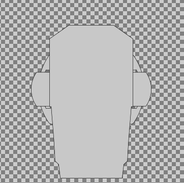
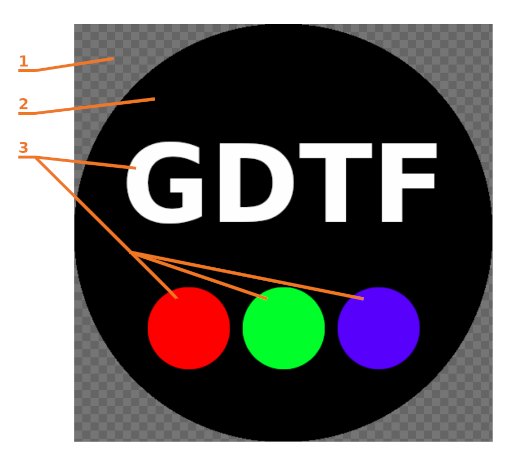
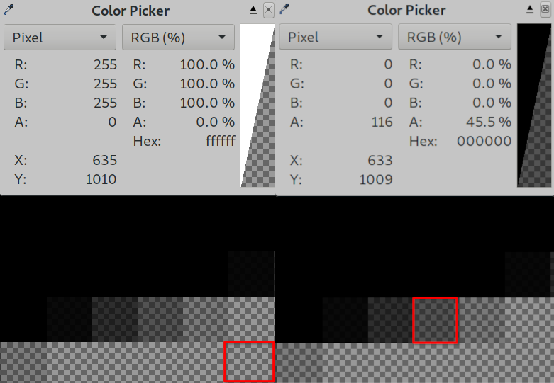
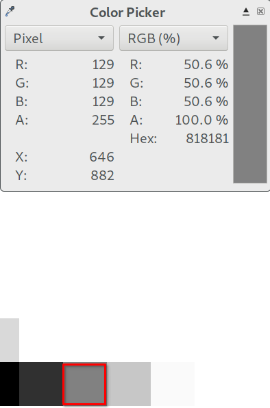
Rasterized PNG images are used in GDTF in several places - as a device thumbnail or as a MediaFileName in slots for gobo wheels and animation wheels. While the definition of a device thumbnail is quite simple (a png file to provide the rasterized picture with maximum resolution of picture 1024 x 1024), definition for a gobo slot image is more involved: Gobo images shall be in PNG format with an alpha channel. Indexed, Greyscale and Alpha, 8-bit RGB and Alpha, or 16-bit RGB and Alpha are accepted pixel formats. The Background shall be fully transparent and should be considered to be the equivalent of a gobo holder. The Image region shall be fully opaque aside from anti-aliasing and shall be as large as possible. The Background region, the equivalent of gobo holder, is defined by full transparency (Alpha 0). In the Image region, Pure Black (RGB 0,0,0) is opaque (2), and Pure White (RGB 255,255,255) is transparent (GDTF). Colored gobos (3) shall use an RGB approximation. The RGB approximation shall be calculated on the basis of Pure White being the CCT of the fixture light source and the ICC color profile embedded within the PNG. The default shall be sRGB. - Maximum resolution of picture: 1 024x1 024; - Recommended resolution of gobo: 256x256; - Recommended resolution of animation wheel: 256x256 So for thumbnail images, one can use pretty much any png image with the given dimensions. Ideally, the image should be a square, so the result in any UI is more predictable. This is the default image provided by the builder: What we like to do, however, is to ensure that the image is actually trimmed on a transparent background, so it can better fit into any UI (checker board indicating the transparency): With the transparency: For wheel slot images, you have ensure that the non-transparent (opaque) and transparent (white, colored) portions are correctly defined and also that transitions between them is also correct. Here is a 256x256 example. We actually provide gobo images in maximum possible resolution (1024x1024), for the best outcome in visualizers. It is simple to sample down if needed. The only exception we currently do are devices with tenths of gobos, like the MiniMe and ProMotion, where we scale the images to achieve close to 10MB size of the complete GDTF file. As i mentioned, critical parts are the transitions. On the edge between alpha and color, you should have no extra color (due to antialiasing), just the alpha (transparency): On the edge between white and black, you need to have only colors and no transparency: Same rules apply for the animation wheel: Hope this helps Petr

-
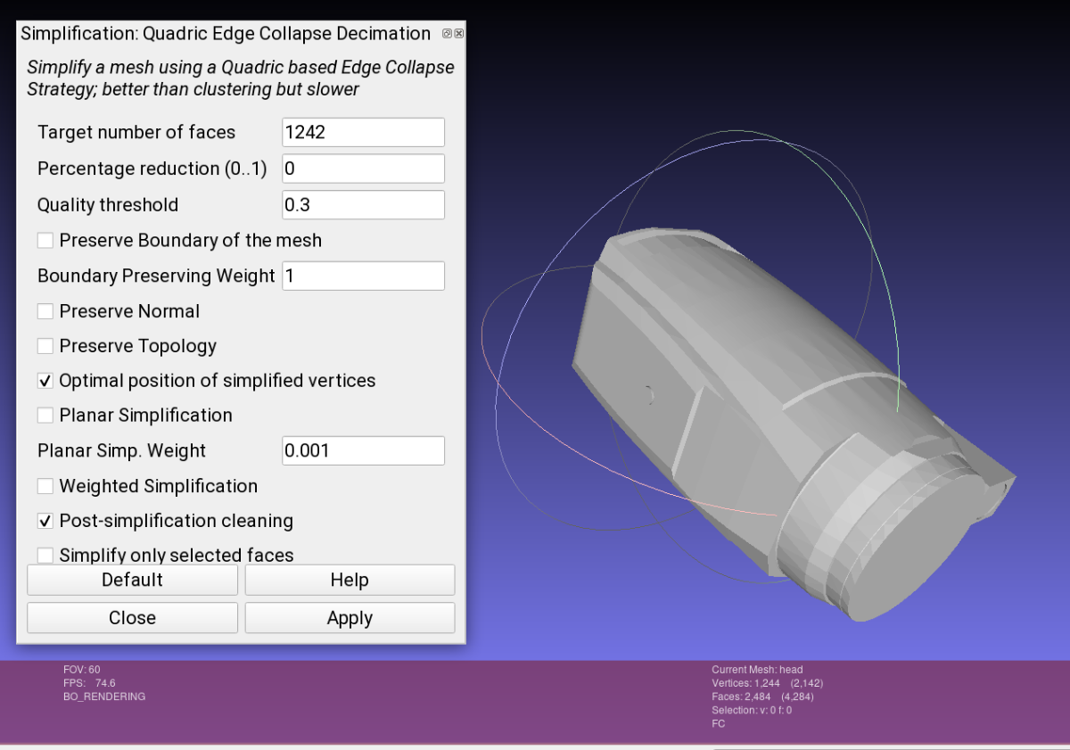
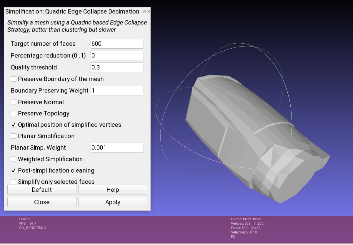
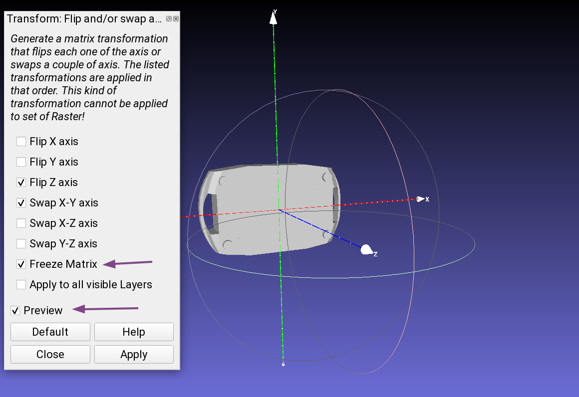
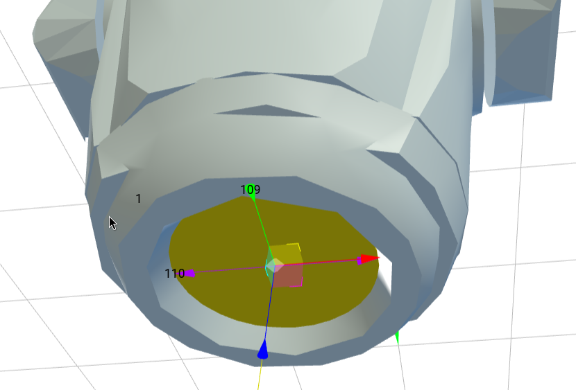
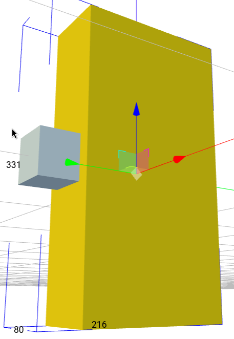
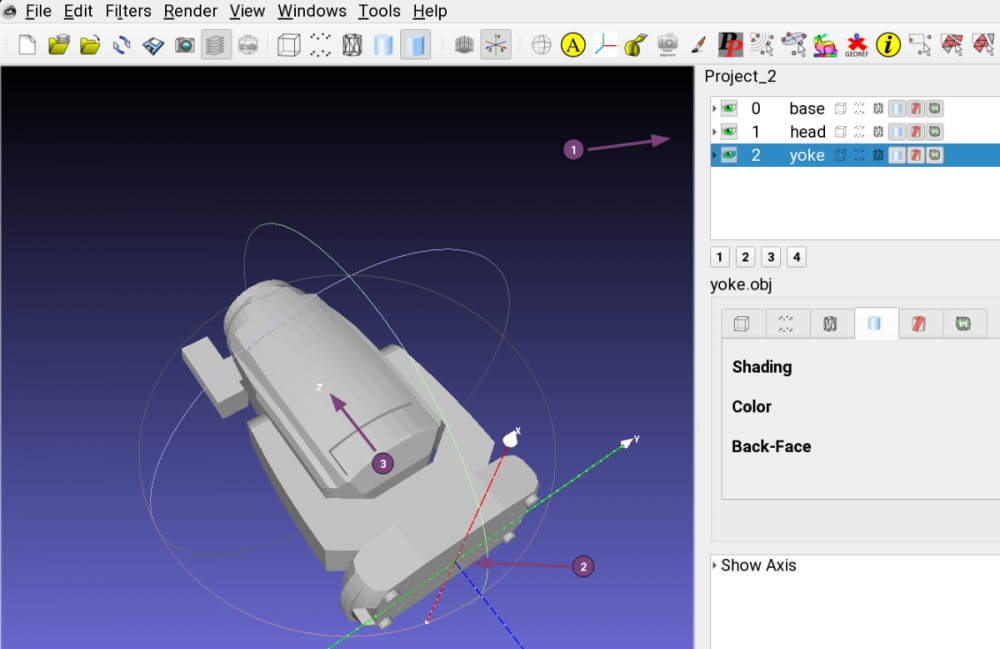
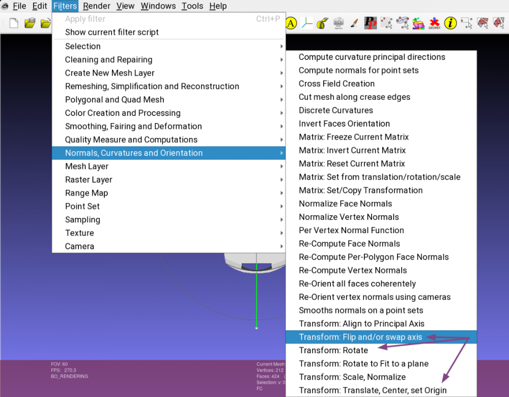
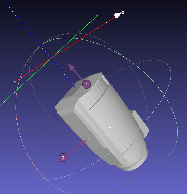
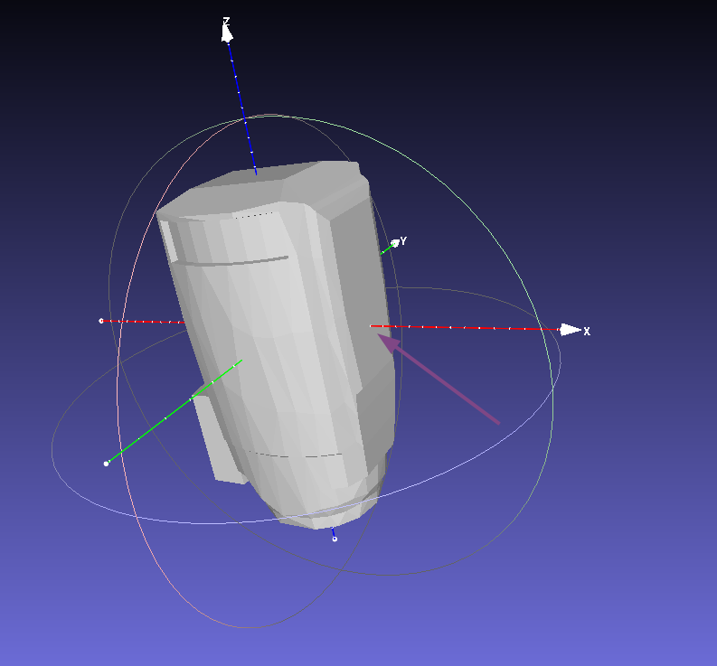
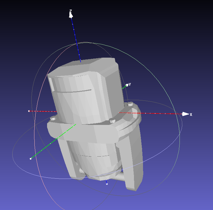
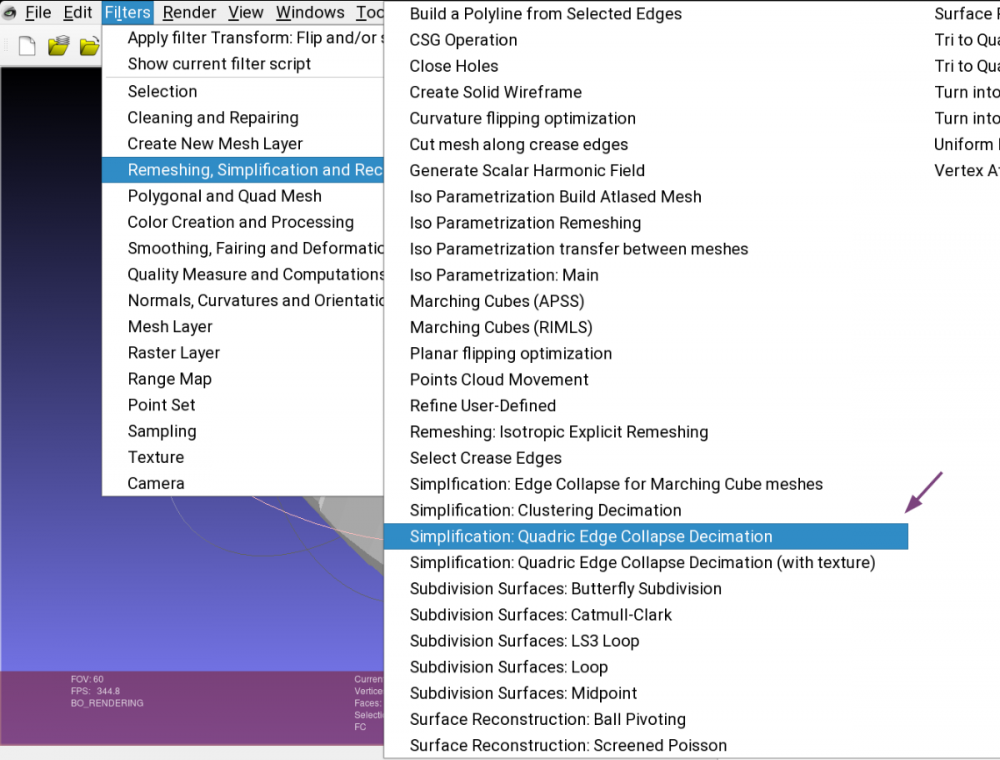
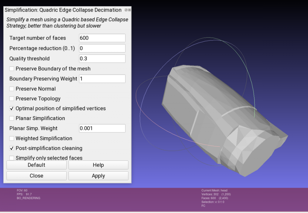
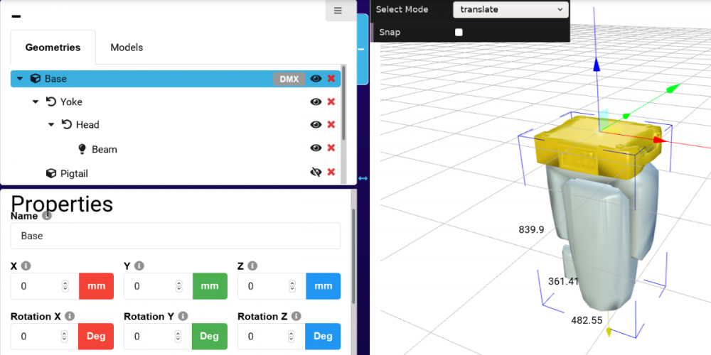
3D models are one of the essential assets in GDTF. Lets see what we need to do to make our 3D files ready for GDTF. You can either use generic 3D models already predefined by GDTF and available in the GDTF builder, or you can provide your models. Models can currently be provided in the form of 3DS files, or in the future it will be also possible to use glTF files. How to create models of the devices is out of scope of this post, what we will look at today is how to modify and adjust existing 3D models provided by the manufacturer for use in GDTF - apply position, rotation, alignment and adjust the quality of the meshes. I like to use Meshlab for assets preparation for GDTF, but you may choose to use other tools, like Blender, Cinema4D or some other software. We will look at a generic moving head fixture with base, yoke and a head. What you usually get from the manufacturer's documentation is a complete 3D drawing, made of individual parts, assembled into the shape of a real fixture. What we need to do for GDTF is to separate each moving part into an individual model and adjust it's origin point and alignment. Here is GDTF definition: The mesh of each fixture part shall be drawn around its own suspension point. The zero point of a device does not necessarily have to contain the offset related to the yoke, but it must be centered on its axis of rotation. The offset is defined by the geometry and has to be related to its parent geometry and not to the base. Which means that in each model's file it's origin point is defining the rotation point. Here is an example of a complete fixture before adjustment, we can see the individual models listed on the side (marked with 1): As you can also see, the origin point (2) is at the center of the base plate, but this is only correct for the base, not for yoke and head, so it will need to be adjusted. Here is another part of the GDTF definition: The device shall be drawn in a hanging position displaying the front view. That results in the pan axis is Z aligned, and the tilt axis is X aligned. 0,0,0 – center base plate. So the device must be drawn upside down, the head must point to negative values of the Z axis and not to the positive direction (3), which means that all models will need to be rotated and adjusted. Your model will most probably be rotated differently, so take this post as a reference. Meshlab allow us to individually select each model and perform operations on it, like Rotations and Positioning (translate) by defining numbers (degrees or digits) of movement. At the same time, it provides a "freeze matrix" feature, which sets the current transformation matrix into the coordinates of the vertices of the mesh (and set this matrix to the identity). In other words, it sets the origin point to the place you need it to be at :), which is what is needed for correct application in GDTF. Here are the Transform tools in the menu. What i like to use instead of multiple rotations is a tool called "Flip and swap axis". One important note: you must always first perform a translation (positioning, to define the origin point - point of the rotation) and the only a rotation, otherwise the rotation would happen along a wrong axis/point. So in my case (your model might be different) we adjust the base by axis flipping and swapping as follows: We can now see that the base bottom plate is facing positive direction of the Z axis, good. Now we need to apply rotation to the yoke and head, because what we have so far looks like this (example of head): The model needs to be positioned (1) and also rotated, so the X axis is defining our rotation (2). You will need precisely measured positions for these offsets, often these will come from manufacturer's drawings or other documentation. Here is the result after applying the Translation and then Rotation in Meshlab: And this is adjusted model of yoke: After we adjust all (base, yoke, head) and If you open all three models together, they will be overlapping each other: This is because the offsets of these models will be defined later, in the GDTF file. For the offsets in GDTF, we will again, need precisely measured values from the device's documentation. Our files are almost ready, but we still must ensure that the models have certain complexity, as for example defining them too detailed (most common case) results in high demand for processing power of the visualizers. You can prepare a detailed, high vertex count file if you perhaps have a demand for a particularly detailed rendering, but for normal operation, you should conform to the GDTF definition: All models of a device combined should not exceed a maximum vertices count of 1200. To ensure this requirement, we must often simplify the model. Meshlab offers it's "Simplification" tool: Before simplification: Simplified, by adjusting the "Target number of faces". See number of vertices at the bottom: Now we can add the models into GDTF in the Builder, here is the result, with corresponding offsets. Here is the base: Yoke: And head: Hope this helps Petr


-
- 1
-

-
- rks
- robe knowledge sharing
- (and 4 more)
-
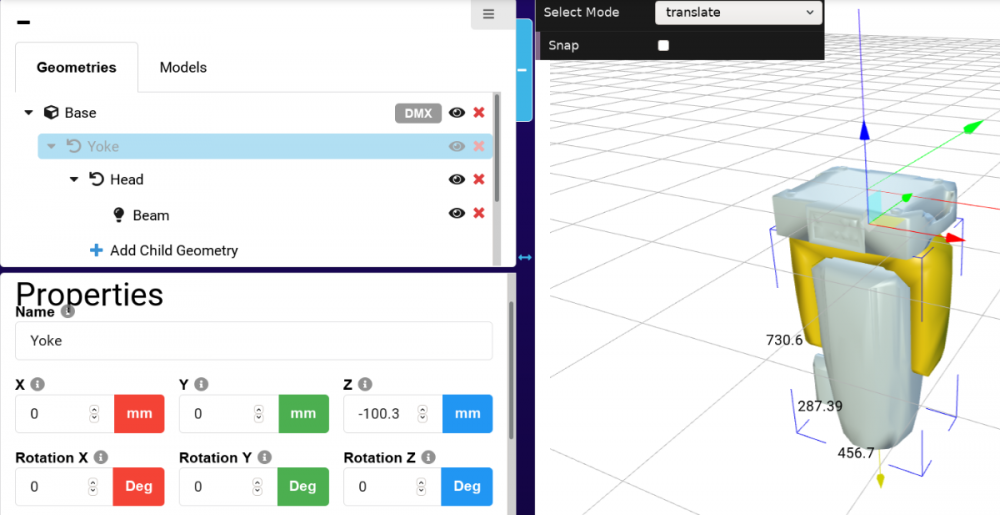
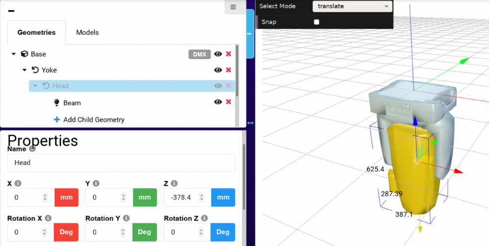
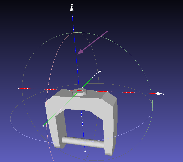
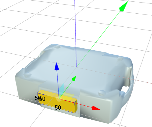
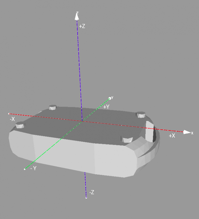
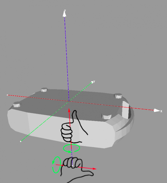
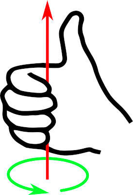
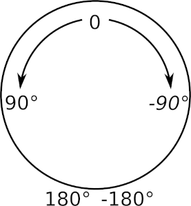
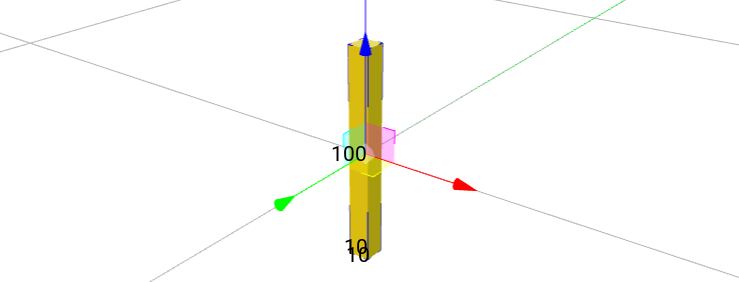
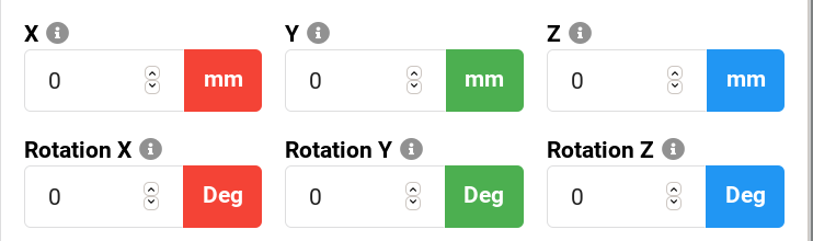
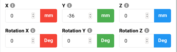
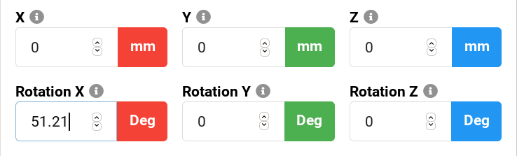
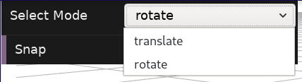
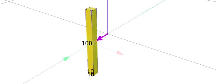
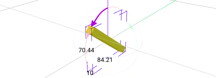
Before you define any physical attributes, you have to make sure to understand how positioning, rotation and orientation is defined in GDTF. 3D space definition GDTF defines this this way: The metric system consists of the Right-handed Cartesian Coordinates XYZ: X – from left (-X) to right (+X), Y – from the outside of the monitor (-Y) to the inside of the monitor (+Y), Z – from bottom (-Z) to top (+Z). For a device, everything starts for you with your 3D model. Here is GDTF definition: The device shall be drawn in a hanging position displaying the front view. That results in the pan axis is Z aligned, and the tilt axis is X aligned. 0,0,0 – center base plate. So this means: the device is upside down the origin point (0,0,0) is in the center of the base plate (meaning, not in the center of the base model, not at the "end" of legs) you draw the device with it's front in the direction of the -Y axis (facing you in the builder) by placing the "pigtail" model, you indicate the location of the panel with connectors or the power cord the positioning and orientation is how it must be done in the 3D model, especially for the base, because the top geometry (often the base) cannot contain any extra defined position (offsets) and/or rotations If you for example decide that the "front of your device" is where the connector panel is, this would be the result: Rotation Here is GDTF definition: The metric system consists of the Right-handed Cartesian Coordinates XYZ. Let me re-phrase this as this is basically the right handed rule: The right thumb points along the Z axis in the positive direction. Positive rotation is shown by fingers curled in the direction of rotation. When viewed from the top or Z axis the system is counter-clockwise. The top here is you, naturally looking at your hand: The counter-clockwise sounds strange, but because in real life you often "observe" it from the bottom, you consider this "normal" for screw threads and so on, because to screw them in, you turn them to the right. This is how it looks applied to the model/geometry, indicating pan/tilt: So when viewed from the top: Positive values are increasing values, so angles from 0° to 360°, from -360° to 0° of from -360° to 360° are positive, angles from 0° to -360°, from 360° to 0° or from 360° to -360° are negative. When defining angular ranges, you typically start from center (0°) and define - and + ranges. Based on this, you can determine how to correctly fill values for pan/tilt angular ranges, gobo rotations and so on. In the builder You can also use the Builder to show you the positioning (translate) and rotation (rotate), you can choose a mode to manipulate the model: Centered: Model: Displayed values: Moved "to the front", to negative values on Y axis: Model: Displayed values: Rotated "in positive (CCW)" direction: Model: Displayed values: Hope this helps Petr
-
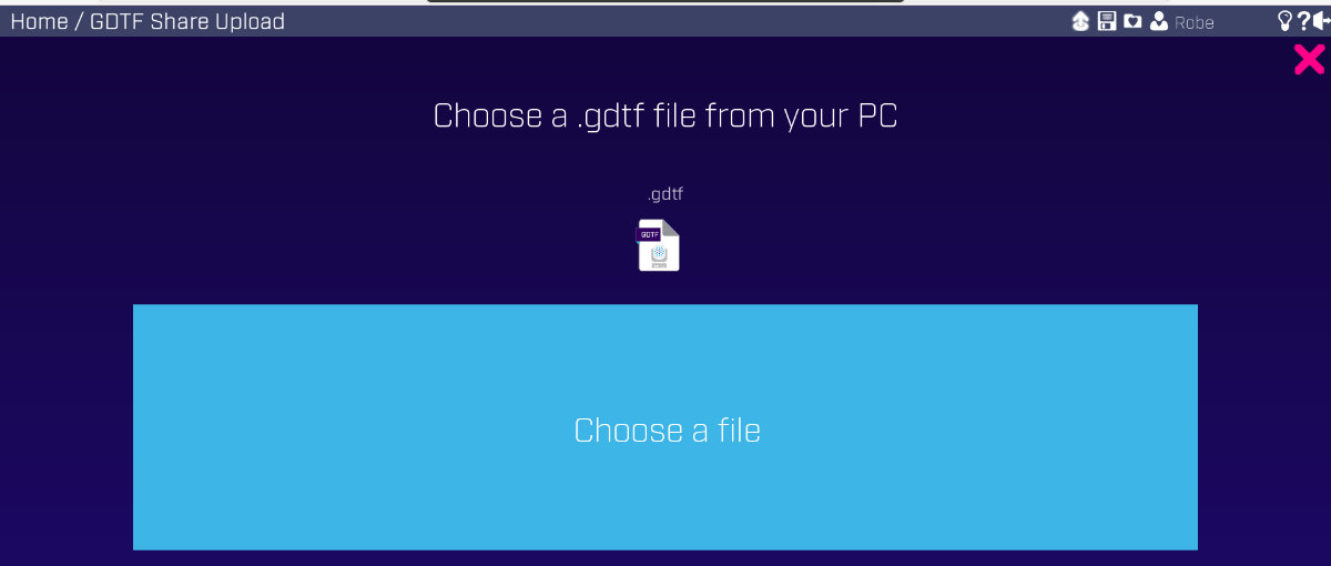
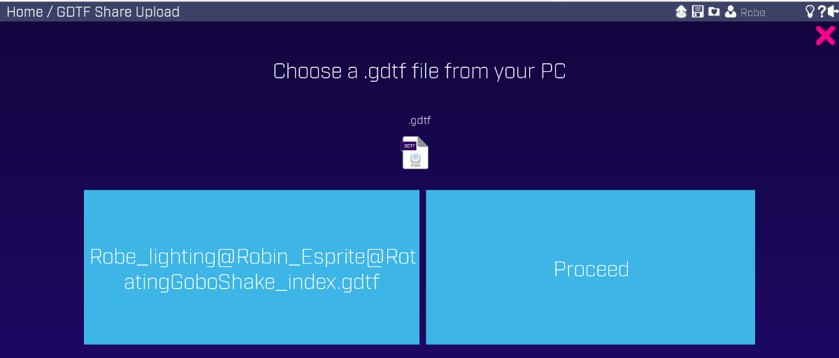
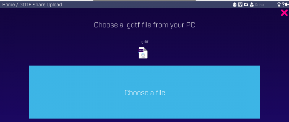
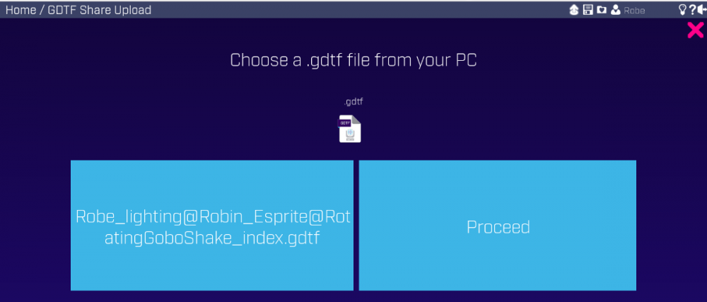
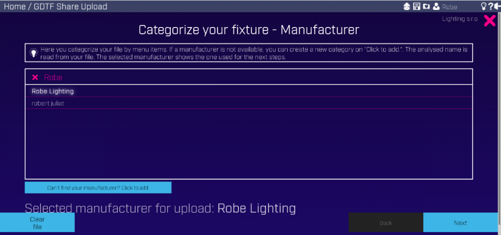
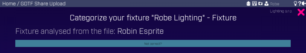
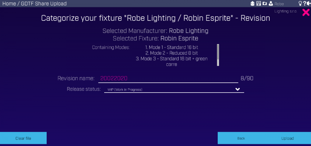
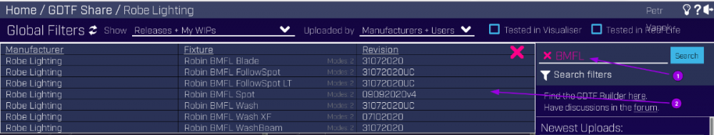
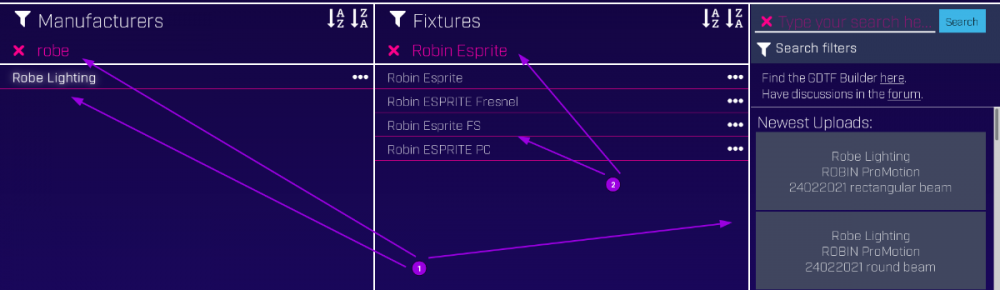
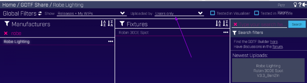
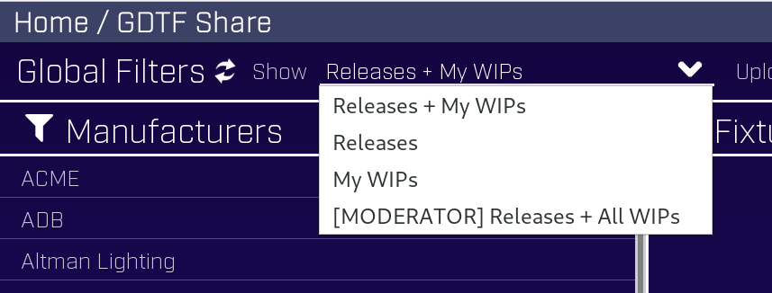
One of the advantages and ideas of GDTF is a central repository - GDTF Share, connected with a GDTF file editor - the GDTF Builder. Using the Share is pretty straight forward - you can upload, search and download files... but in reality there is much more going on behind the scenes. The Share contains powerful filtering and management system to ensure that this repository is kept nice and tidy, while at the same time any random person still can upload a GDTF creation of their own for others to use. Lets look at that... Searching and filtering Users can search the Share easily: Each file "belongs" to a "folder" of the vendor/manufacturer of the device and then a "subfolder" named by this "device name", with relevant filters: 1) filter for a manufacturer 2) filter for a device name File can be released to the public or can be in a Work in progress (WIP) release state. The WIP status is assigned to files by default and allows authors to keep working on their files and continuously saving their progress... plus their filters: Files are divided into being created by "users" and "manufacturers", the Share then contains respective filters: There are also various tags like "tested in 3D", tested in real world... and their respective filters: File upload To ensure that files are well organized, the upload process contains several steps to assign manufacturer and device. The Upload icon is up at the top: You can choose a file: And Proceed: Manufacturer is automatically detected, but you can also choose if if required: Same for the device name: At the end of these dialogs, you can review everything and can name the revision plus set the status (Released or Work in progress): Manufacturer moderation Manufacturers have special power that allows them to manage "their" folder to keep it organized. To use their "moderator" tools, there is a "Moderator" in the "Show" filter: This allows manufacturers to rename the name of their folder. This is why Robe folder is called "Robe Lighting" while the name of our company is "Robe lighting s.r.o.": Moderating operations can be done on device "subfolders" or on individual files - folders can be merged and renamed: Individual files can be also moved around or have their Revisions renamed: Manufacturer's pages Each manufacturer also has a dedicated page with a representative listing of the files for their devices, here is what it looks like: Hope this helps Petr See all Robe Knowledge Sharing Articles.


-
First steps of getting into GDTF... let's get right into it. Accounts Create and account in https://gdtf-share.com/ so you can access the Share, Builder and the Forum. Sign into the forum at least once, so your account is activated here. If you are an industry related vendor (for example a manufacturer) drop an email to info@gdtf-share.com , together with brief introduction about who you represent and your Share username. This will provide you with the possibility to enable manufacturer account in the Share and invite to the monthly GDTF manufacturer's interfacing meeting and discussion. If you are after the formal GDTF Specification, get the DIN SPEC 15800:2020-07 . As this is an official DIN document, distribution is possible only through the DIN publishing body, Beuth in this case. https://www.beuth.de/en/technical-rule/din-spec-15800/324748671 GDTF Authoring To create the GDTF files, best way is to use the Builder. There is a quick manual here, so make sure to check it out. But there is nothing like just doing it, over an over again. As with any tool, it is very simple to make a simple basic file, but it takes time to learn the tiny details. Get some inspiration from existing files, the Share offers a lot, we at Robe have also been creating files for all new (and even older) fixtures, so this can serve as a lot of inspiration. Here are few examples to get you started: Very simple tungsten device even without dimmer (but the file provides a single channel control for visualizing purposes), Patt 2013. A typical discharge spot , a moving head fixture, the BMFL, with gobos, prisms, iris... using Mode Dependencies and other features required for a moving head device. A multipixel but single RGBW controlled small LED beam, the LEDBeam 150. For a linear LED unit, check out the VC-Strip 25 8x1. Going up with complexity, a multiring LED wash fixture, the LEDWash 800. For a fixture with many DMX modes and Mode Dependencies, look at the Orbiter. If you need an example of quite complex pixel controlled LED fixture, Tarrantula can be an example. This is also showcasing custom 3D model for the beam pixel lens. Start with visualizing right away Several manufacturers are working on their GDTF implementation. Check out what they are offering and maybe ask for support if not announced yet. You can also use GDTF files right away with either MA3 or VW Vision and although there is always room to implement more niche details, most features needed for the real day to day operation already work very well. Start with a basic device and see what it looks in the visualizer. This allows you to work without a physical fixture and you can explore and test even complex depths of GDTF possibilities. DMX controlling versus general device description For basic DMX controlling, very simple GDTF file is all that is needed, so i would suggest to start with that, but GDTF offers much more, from the 3D models through connectors to real world physical parameters. For that, you will need real measurements of real devices, but again, you can try any values for the start, to get a feel how to enter them into the builder and what the visualizing looks like. Consuming GDTF data If you are more into utilizing and using the GDTF data, definitively check out the DIN Spec as per above. Also, look at the GDTF XSD file and PR for a Schematron validation file (kindly provided by @Janng ). There is also the libMVRgdtf parsing library (ask for access through the info@gdtf-share.com email as per above), or if you like to use GDTF fixtures in a 3D game engine, you might also like to check out the Unreal Engine GDTF implementation, described for example here. As the GDTF format is completely open and there are already some well performing devices files in the Share, is it simple to start with implementation and do some experiments of what the GDTF can provide you with. Hope this helps Petr
-