-
Posts
506 -
Joined
-
Last visited
-
Days Won
49
Content Type
Profiles
Forums
Events
Everything posted by Petr Vanek - Robe
-
How to modify the path in the information table in GDTF
Petr Vanek - Robe replied to MA3 YIN's topic in General
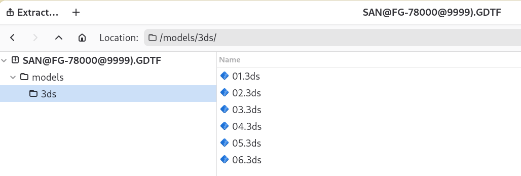
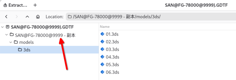
Hello @MA3 YIN, the issue you have is that you created an extra folder called "SAN@FG-78000@9999 - 副本" in the GDTF file. This folder "SAN@FG-78000@9999 - 副本" must not be there: It has to have this structure: Hope this helps
-
Hello, i looked at the file and the 3D files have incorrect file name, someone/something added "3ds" to the name. The name should only contain the name of the file, not the name of the folder. Once the filename is correct, the builder shows the file correctly. See attached. If you modify the files by hand (i presume that this was the reason), you need to be careful. SAN@FG-780@QWRV1.2.gdtf
-
Pixel Orientation
Petr Vanek - Robe replied to mgeasey@clearallvisualsllc.com's topic in Discussions
As control channel change is not persisting on DMX, one cannot use the Mode Dependencies structure for this, but a new geometrical tree with new pixel layout can be created to accommodate it, the device would need to be re-patched. -
Hello @Quillons, i am not sure if i understand the question. But... a customer attribute will allow you to get a control in the DMX desk, but will do nothing in a visualizer, as visualizer companies look at the attributes and implement one by one into their system... for Dimmmer, they make "light objects" to change the intensity... and so on. So a custom "MyFog" will give you "MyFog" encoder in the console, but will typically do nothing in a visualizer.
-
Mat panel with light (fixture where the surface is the emitter)
Petr Vanek - Robe replied to Sylvest's topic in General
Hello @Sylvest i would suggest to look at the GDTF training videos, they will give you an idea. Attached is a simple example of an emitting mat with just a dimmer control, not sure if this is what you are after but together with the videos you should be able to make it to suit your needs, hope this helps, Petr User_Test@Emitter_Mat@initial_version.gdtf -
I see. For such a thing, using the API is the right thing to do.
-
Hello @dnadoba,this is normally up to your software code to handle and check if the session is still valid and if not, re-authenticate. I have personally not seen any issues with this. Or are you downloading stuff manually? That is not the intention of the API...
-
GDTF LogicalChannel Mastermode clarification
Petr Vanek - Robe replied to Nikolaus Einhauser's topic in General
Hello @Nikolaus Einhauser, the "Grand" is meant as a "Grand master", the "Group" would be a submaster - if the console supports such a concept, and yes, it would interpret it based on the behavior it offers. -
Only in RGB* modes, in the default CMY it works OK.
-
Here:

-
The GDTF Booth at Prolight & Sound 2025 will be at Hall 12.1, stand C43. Come to visit us for 💻 Live demos, 👕Exclusive swag, and 💡Expert Insights.
-
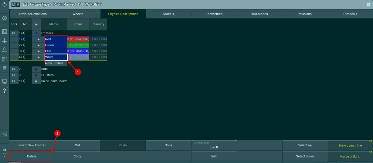
Hello @teclim, at the moment, this is known behavior of the gMA3 visualizer on fixture files which contain real world color measurements. You can eliminating this either by disabling the White Point 8000K in the Robe physical fixture or by unlinking the RGBW Emitters from the RGBW attributes in gMA3. Kind regards Petr
-
Hi @Paolo.Prolights, we were able to replicate the original report, but it seems that this new report is the same as the previous one, or what exactly is the difference?
-
Channel Sets physical values reset to 0-1
Petr Vanek - Robe replied to Prolights's topic in Discussions
Thank you. I will try to replicate and will report to the developer team. -
Hello all, we have launched a Developers page on the GDTF Share website, to provide easier access to information about GDTF/MVR Specifications and developer resources. You can see the page here.
-
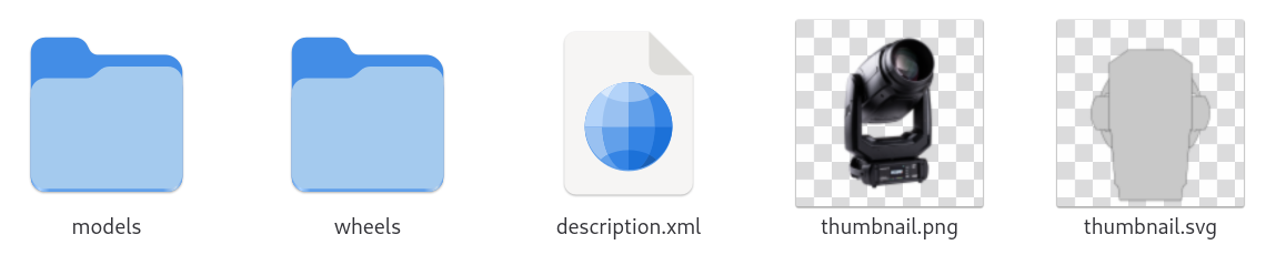
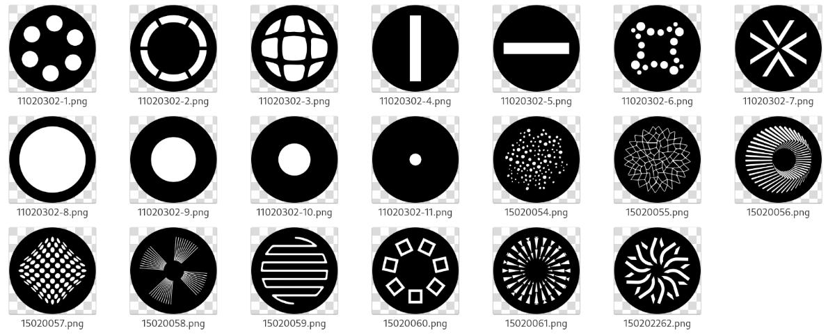
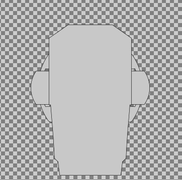
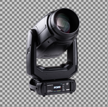
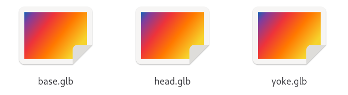
Extracting resource files directly from GDTF Sometimes it may be useful to extract some data like gobo images, 3D models, or other files directly from the GDTF file. This is possible, because every GDTF file is a zip archive with .gdtf extension. To access the content of GDTF, rename the file from .gdtf to .zip and then open as any other zip archive. When you unpack the .gdtf file, this is what you can typically see: The description.xml file contains the description of the device type. There is a lot of information in this file and it requires deeper understanding of the GDTF Specification to utilize it: The thumbnail.png provides an image of the product: The thumbnail.svg is providing a 2D symbol for planning tools: As these are normal .png and .svg files, they can be copied and used directly in any supportive application as needed. The wheels folder contains all the images for gobos, animation wheels and so on: The naming of the files is up to the GDTF creator, while the details of the image are as far as format, resolution, color conventions and so on. The models folder contains subfolders for 3D and 2D models, for a better structural overview: ./models/3ds ./models/gltf ./models/svg The existence of these folders is optional and depends on presence of files specific to these folders. If the GDTF file does not contain any .3ds files, then the folder ./models/3ds will typically not exist. If the GDTF files contains 3D models in gltf format, then they will be in folder ./models/gltf, the content of the folder then may look like this: These .glb files can be used in applications utilizing 3D files. The positioning and offsets of these 3D files has been previously explained in several other RKS articles and is also defined in the GDTF Specification, together with more information on the possibility to define also 2D models, 3D models in higher or lower level of details and so on. For the most time, extracting 3D models and gobo images in what is needed. For the examples above, we used the the Robe Robin LedPOINTE, which is available in the GDTF Share here. Hope this helps, Petr


-
Hello all, we have released another update to the GDTF Builder. This was mainly a maintenance and bugfix release, where we updated the underlying dependencies, improved the project structure and fixed several issues. Bugfixes and improvements Fixed and issue with open url causing infinite recursion Fixed an issue where a Channel function could not be set to cover DMX 0-255 range Fixed an issue in Duplicate and arrange geometries - when using Address offset, the first address was missing Fixed an issue where Rotate Geometry did not work as expected when using the up/down arrows or the mouse wheel Fixed an issue where the Drop down for "SubPhysicalUnit" was cut off in SubChannelsSets section Fixed and issue where the Fixture type SVG was not being displayed reliably Improved the WIP message in the Save dialog Updated the semantic-ui package Updated to new version of nodejs Updated the build system
-
Channel Sets physical values reset to 0-1
Petr Vanek - Robe replied to Prolights's topic in Discussions
@Paolo.Prolights can you still replicate the issue? I cannot, but perhaps there is something i am missing? We did release a new builder on Monday... but i don't think we were intentionally fixing this bug. Thank you for letting me know. -
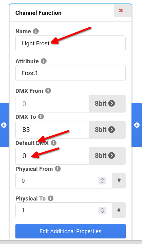
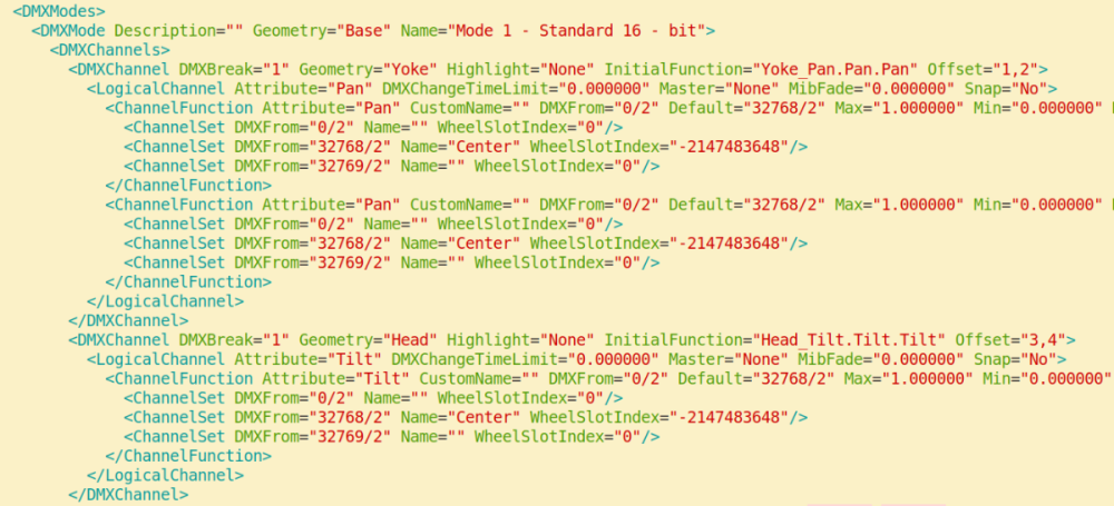
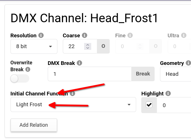
Hi Nicolas, perfect. You would choose the channel function defined in the InitialFunction="Head_Frost1.Frost1.Light Frost" field, so sometimes it may be the first one, sometimes not: <ChannelFunction Attribute="Frost1" CustomName="" DMXFrom="0/1" Default="0/1" Max="1.000000" Min="0.000000" Name="Light Frost" OriginalAttribute="" PhysicalFrom="0.000000" PhysicalTo="1.000000" RealAcceleration="0.000000" RealFade="0.000000"> Hope this helps Petr
-
Hi Nicolas, sure, here is how you get the value: The same in XML, default in the correct ChannelFunction: InitialFunction="Head_Frost1.Frost1.Light Frost" <ChannelFunction Attribute="Frost1" CustomName="" DMXFrom="0/1" Default="0/1" Max="1.000000" Min="0.000000" Name="Light Frost" OriginalAttribute="" PhysicalFrom="0.000000" PhysicalTo="1.000000" RealAcceleration="0.000000" RealFade="0.000000"> Hope it helps, cheers, Petr

-
Hi Nicolas, i trust all is well 🙂 We already have the defaults, these are providing exactly what you are asking for, i have described it recently for someone here:
-
Hello, the API is described here: https://github.com/mvrdevelopment/tools
-
Problem making Virtual Channels work as expected
Petr Vanek - Robe replied to r2.lighting's topic in Discussions
Good morning 🙂 Not a UI bug. A Virtual channel is always at current maximum resolution - a 32 bit channel, then, it is displayed based on which representation you choose (percentage and so on). A Virtual channel does not generate any DMX on it's own, but it can have an effect onto a geometry in a visualizer or you can link it to other channels, which then generate DMX output, this is often called a Virtual Dimmer. More informal information on that has been added to the GDTF Spec here. As for the "Follow topic", i have a feeling that emails are sent only later in time, but i a forum admin would need to respond here. -
Problem making Virtual Channels work as expected
Petr Vanek - Robe replied to r2.lighting's topic in Discussions
Hello, as for the representation of the Virtual Channel, it is a channel which does not produce any real DMX output and is always represented in the Builder as a 32bit channel. As for the Virtual dimmers - this partially depends on how you define the geometries in the fixture (sometimes one has to add extra geometries for the geometry tree to have correct level of depth to react as expected). I do not know this particular fixture so it would be the best to get in touch directly with MA, as the specific sub-fixture assembly logic is partially a gMA3 thing. I will notify the MA guys to have a look here. -
BIG Issue on create Master Mode Dependencies
Petr Vanek - Robe replied to Ale_Zakko's topic in Discussions
Hello, glad to know you have have figured it out. As for the ChannelFunction DMX FROM value 255, that is currently a bug in the Builder and it will be fixed in the next release.