
-
Posts
123 -
Joined
-
Last visited
-
Days Won
11
Content Type
Profiles
Forums
Events
Everything posted by Rex_P
-
Don't ColorForce series of fixtures have a Left--Right or Right--Left internal mode to 'swap' the 'patch' of the fixtures? Would that be an example of such a request?
-
For things to parent 'correctly' inside MA2 and render correctly, you may need some specific Geometry Helpers in your base model for things to offset in a visually correct way. Perhaps if you build the GDTF fixture as you do a MA2 fixture needing parenting, you'll get a more visual result/solution...haven't tried it yet; but it's something I've been postulating inside the ole 'hardhat',;), if you know what I mean...as I consider what renders in MA2/MA3 and how fixtures are constructed with regards to 'helpers'. GDTF would seemingly make strange modeling constructs unnecessary moving forward in how we describe 'fixtures' when they render... If your target is MA2, I'd write the file in 1.5 FixtureBuilder or in a MA2 emulation/onPC...beat the Christmas rush, as it were and I often say. 'Conversion' most often does not parse 100%. Until all console manufacturers get in line with the evolving GDTF; it's a matter of keeping the 2 things separate, as we did when using custom models and Multi-Instance fixtures between v3.1.2.5 and 3.2+ and adjust accordingly. M'eh, what ya gonna do?
-
I don't believe the MA2 reads the GDTF format so you could not use that '3D' symbol[lost on what you mean by that]; I could be wrong, I didn't install v3.8 of MA2. MA3[which I have loaded onto a machine], will read MA2 fixture profile files but I believe they need to be exported to MA3 format, not 100% certain of that. I do know that there is a new file type of the .XML we used to have in MA2, pxml. it is now...proprietary xml perhaps? Used to be XMLP, lol.... The same 3DS model representing the fixture; yes those do not change and it does follow along inside a nested folder within the GDTF file, but not for MA2 consumption. The models are the same; 3DS files, it's in how the MA engine reads them as a profile, that is how it will or won't render or load as a fixture. MA2 needs to read 3D assets out of it's proprietary gmamedia database format....still a 3DS model, but nested inside the database for MA2 to read and render.
-
I'd say, "NO", you cannot move the Root Object/Top Level Object away from World Origin. Give that Geometry/Model a Size of 0,0,0--Quick and dirty 'Gaming Hack' to have something needed within the Scene, without it rendering....placeholder for a 'Parent'....as long as it works; Rex doesn't care about semantics....or utilize the "Body"/Normal Geometry as a starting point. Alter the Size BEFORE you Parent the objects together[in Model Tab], ahem, or you may make the entire object non-rendering, Child/Leaf objects tend to follow their parent object in Scale,Position,Rotation...typical 3D 'math'...LOL, once they're parented/nested. Seems you'll always need a Root 'placeholder' Normal Geometry model/object to avoid the "Can not move/rotate Base object" prompt, as it's from which all the other dimensions are derived. Makes sense; need some sort of Zero Reference Point/COM.....to start things going.
-
DMX value choice always seems to jump back to Percentage? While trying to setup ChannelSets and FunctionSets for a GoboWheel, the ChannelSet DMX From/To columns always seem to default to % when you page away, always finding myself with jumping values, at %50 is hard to achieve with 8 bit 0-255 value range; I put 127, the UI switches to 49%. The value reverts back to %, even if I want to use straight 0-255 range. I enter a value in the columns to find it going Red, because of the range...I'm constantly 'out of range'/red with the switching value, either Percentage or 8-bit. Even the Channel set value range seems to jump to %, even though I want 8-Bit range[0-255]. This sometimes causes Slot 1 of a wheel FunctionSet to go Red because it hates the integer of "0"....does not compute to a valid % range.....takes filling out the entire set of Functions....and still stays red if I switch to 8-Bit readout.
-
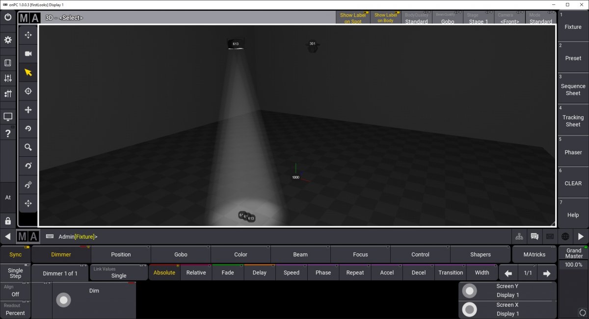
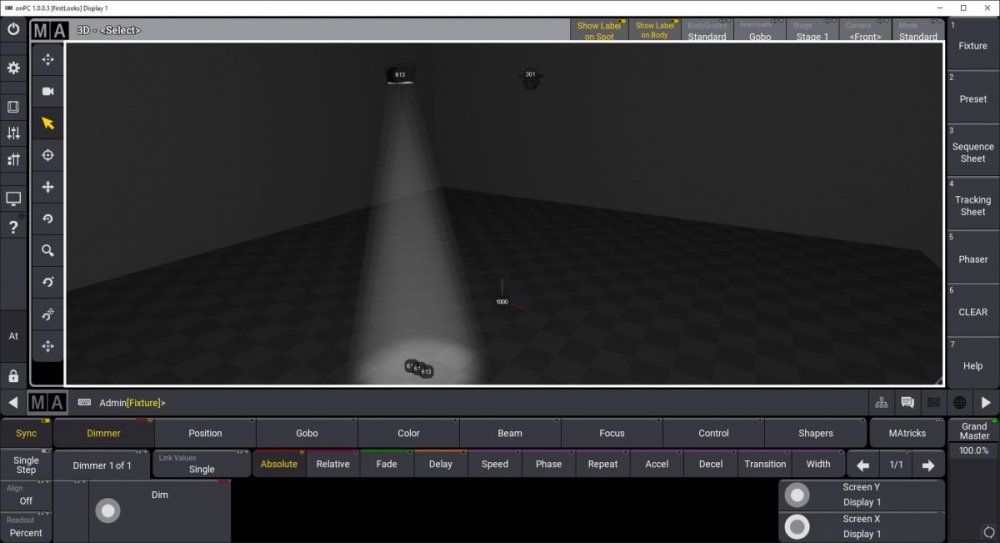
Here's an image of how it renders in MA3. Single Body, multiple Beams, all have Same FID, 613. These are in a line configuration, but just as simple to create a 'ring' of Beams on a single fixture, all from same Attribute. Rex Kinda nice seeing the FID on each beam object, ? Good work GDTF Team; Attributes 'falling through' to children objects; again, seems logical to Rex?, !
-
Where is the DIM [dmx] attribute located in the fixture? Sounds like you want to create a 'blinder' or multi-patch fixture; where there are multiple beams under the control of a single attribute? I can create a 'blinder' that does not toss any errors on geometry placement... MA3 reads this fixture/profile as a 'multi-patch' fixture, single DMX channel controls multiple Beam objects within the fixture, no sub-fixutres. Now, there is some very goofy offsets if you use multiple models to represent multiple parts. I generated this fixture by only using the 2 models within a default Conventional GDTF profile. Got a simple audience BLINDER which renders in MA3 off of a GDTF formatted file. GM master controls every Beam object within the single Fixture visualization... I normally do use Geometry References when constructing subFixture profiles[multiple channels of single Attribute], but simply utilizing another 'Geometry' object to accept the DMX from the Body and visualize, all seems to work out nicely and logically. Same Attribute[DIM] to a Parent Geometry, place multiple children Geometries, seems to create multiple copies of same Attribute--exactly what a multi-Patch[MA2] fixture represents when visualized. I wish MA2 understood what a piece of Geometry/Model can be used multiple times within a profile for... What fixture are you attempting to profile in GDTF?
-
Yep, I can confirm that vGobo does parse over to MA3....FTW! Took all day delving into this new software, lol. The Wheel Assignment to Link the Wheel to the Slots needs to be in a better location, outside of Advanced subDialog, ;P, or at least a notice of which wheel to each Channel Set is active.
-
Think I found my error....lol.
-
Just checked for myself in MA3... Thanks, mate, my models and the GDTF file that I wrote for it works great with virtual attributes! Just need to get my gobos in the MA3 asset tree and they should render on my vGoboWheel I put on the fixture as well, nice they're allowing 'virtual' attributes to render with no DMX waste. My vPan and vTilt work just fine and now they work with the console encoders as well!!! Just have to remember; they get cleared with all other commands in the desk and should have their focus positions stored as a Preset to keep them 'static'. Seems no way of interacting with the 3D environment as we did in MA2 to have this work, too bad.... For 'Blades' I found with the existing MA2 scheme that all you needed to do was give the attribute to the fixtureType and the MA2 internal 3D engine automagically did the rendering to the profile's attribute. Blade seemed to have it origin of rotation to be center of blade on the 'inner side' of the blade.
-
Gonna be up to MA International to get MA3 3D space rendering all the data....I think to get these objects rendering/functioning... Interesting about 'virtual Pan/Tilt' Tim, this works in MA3 without DMX channel assignment? By giving the geometry the appropriate 'helper'/tag and locating it correctly in 3D space upon Importing. My ETC Source 4 ERS is based upon this concept which worked great in MA2 3D, I could drive the fixture's helpers in the MA3D interface; seems those days are gone with MA3 3D....unless they work, 'out of box' by utilizing the GDTF paradigm.
-
Probably never. MA3D did not handle Materials and UV mapping very well and was fairly useless in the way of memory wasting on the rasters and UV mapping....You will never see the data in the Fixture Builder but this doesn't necessarily mean that the final 'rendering solutions' via the various Visualizers won't show the data, ?. The Bitmaps and UV coordinates 'should' be maintained within the 3DS file used as reference in the GDTF file structure. Thus any rendering software can visualize the data. The online Fixture Builder is just that; a parser of the data, it's not intended to be a final visualizer. Attribute control and DMX config, it seems....my take-a-way with the Fixture Builder. It will take a Visualizer producer to generate a solution as quickly as possible for evaluation and feedback. There is absolutely NO feedback on the format from a rendering standpoint at the current and we keep 'expecting' this web based Fixture Builder to fill in the blanks; it will probably never do so.
-
Thanks for the update, Petrvanek, and I agree with generic 'units' of 3DS models, it's how C4D conceptualized 'units' before a certain version[R12 I believe], but now the program understands the various systems for measurements/conversions and can convert on the fly. Yes, even when I try to set the UI of the Importer to M, it resets to MM and stuffs the "2" integer in the slot, so I get out of scale model....I'd love to manually specify 'units' upon Import, would seem to solve any scaling issues between Exporters of 3DS.
-
Ya, Builder seems to hate C4D 3DS files....I Imported a random 3DS object/model from the web and the size was respected, so go figure? Never had a C4D model to be out of scale/size, except in this web based builder...seems to always bring in the file at the MM scale, taking the Unit value and stuffing into the MM wrapper, imho? All I got, being a 3rd party 'observer' to the process...lol. Did you try some other 'flavor' of 3DS export? Did they all get borked size as well...? Coming from Max or Solidworks? No word on what was utilized to create the online Builder. But, ya, I open my 2M cube anywhere else and it's a 2 Meter Cube...? Wacky!
-
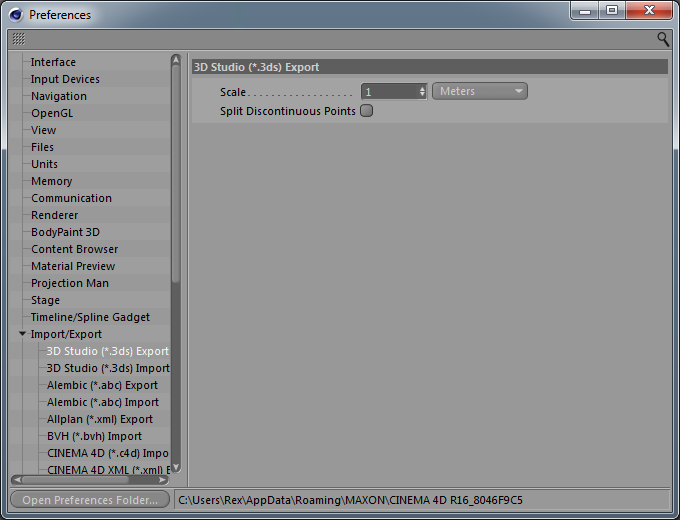
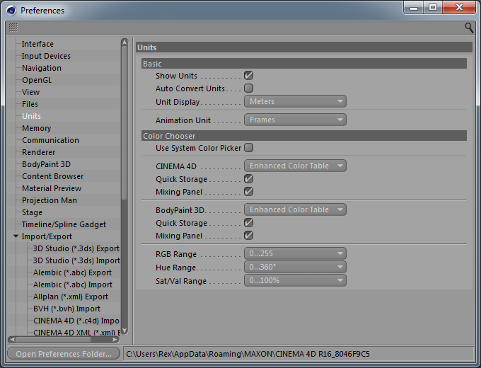
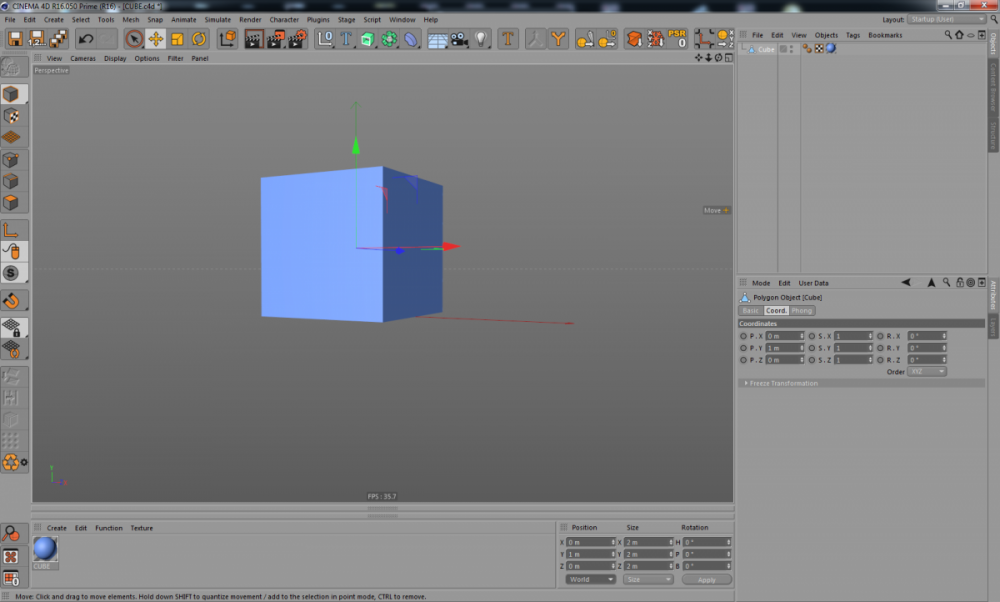
It must be how C4D exports 3DS files, as this file is definitely not 2mm per side in C4D, it is 2 M x 2 M x 2 M...the default Size of the Cube Primitive in Cinema4D?? Here are the Preferences for Exporting 3DS files from my copy of C4D: Meters Here are the Preferences for Displaying Units in the C4D Interface: Meters Here's the 2Meter Cube in the C4D Scene. Notice Size is 2m, not mm. I've been Exporting 3DS files into MA Lighting MA3D for several years now for 3D visualizations; never had issue with Size or Scale of the models. Now, 2 programs say it's actually set to mm's...??! amazing and hard for me to believe actually...??? And I just checked in another 3D modeling/animation program I have and it said 2 Meter Cube...go figure?!
-
Oh, I agree, by changing the values manually, I do get a rendering now. This, to me, is not respecting the file's Size. I set the UI to Meters, it's Exported at Meters. It arrives as 2 mm...even when I set the UI to meters and have to again, as before, set the Size manually...the original observation I made on this build. For me, checking the box, does nothing as an improvement and the default Units of the UI don't seem intuitive... Ya, every time I Import this cube, it arrives at 2mm instead of it's exported units, Meters....even if I set the UI to Meters...that is not intuitive at all, imho. Rexy
-
Another observation:: This model was exported at the Size of 2Meters each face. Even when I change the UI to use M as my units the Import arrives with mm as default Size/Scale...
-
Certainly, glad to help. Here's a simple Cube primitive, exported from Cinema4D as a 3DS file AT Units set to Meters in the C4D Scene, exported at units set to Meters to 3DS. Geometry had Material[no bitmap] applied to it with UV mapping and a Phong shader set to ~80+degrees angle. Do a straight up Import using the Fixture Builder. When you Import the 3DS file, it's got size values now[with this test model] and a vert count, but no rendering in the UI? None of my earlier Imports of 3DS files had this issue?CUBE.3ds
-
Pretty much the same issues on a Windows10 laptop, Chrome, different 3DS file. Still very goofy Import.... The model I just uploaded has entirely wrong dimensions as it is not 2 mm x 2 mm....does have only 246 Verts, which should fall within the range to render, iirc, as to limitations on a 3DS model. I had no problems on the earlier version of the Builder, just sayin'....and now with new build and new features, I got's problems uploading...again, just sayin'...I have an observation; not saying it's right or wrong, it's what I'm observing at this moment in time, ;). Anyone else had no problems earlier but now do?? Just askin'... Rex
-
or this Windows 7 machine, cause IE can't even render the Fixture Builder page log-in page[no entry fields just blue background] on this same computer/device. I'll investigate more with a Windows 10 laptop shortly...
-
Me starts to think it's in the Tabs and the entry fields....not linking the data? All I got at this point.
-
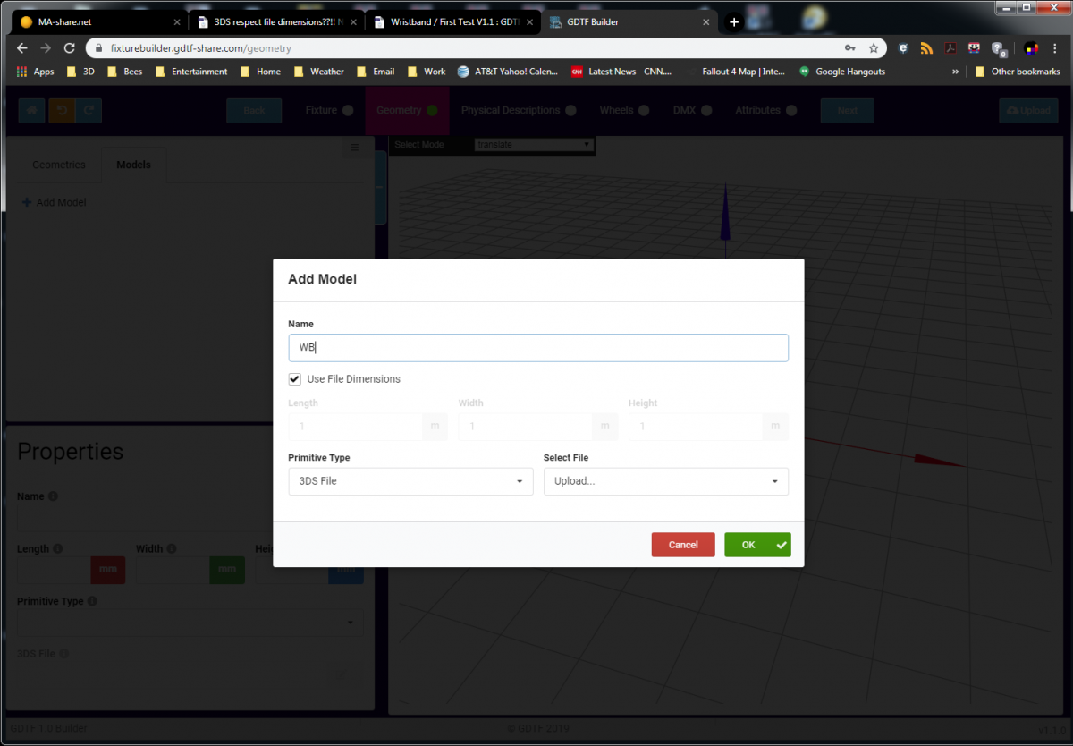
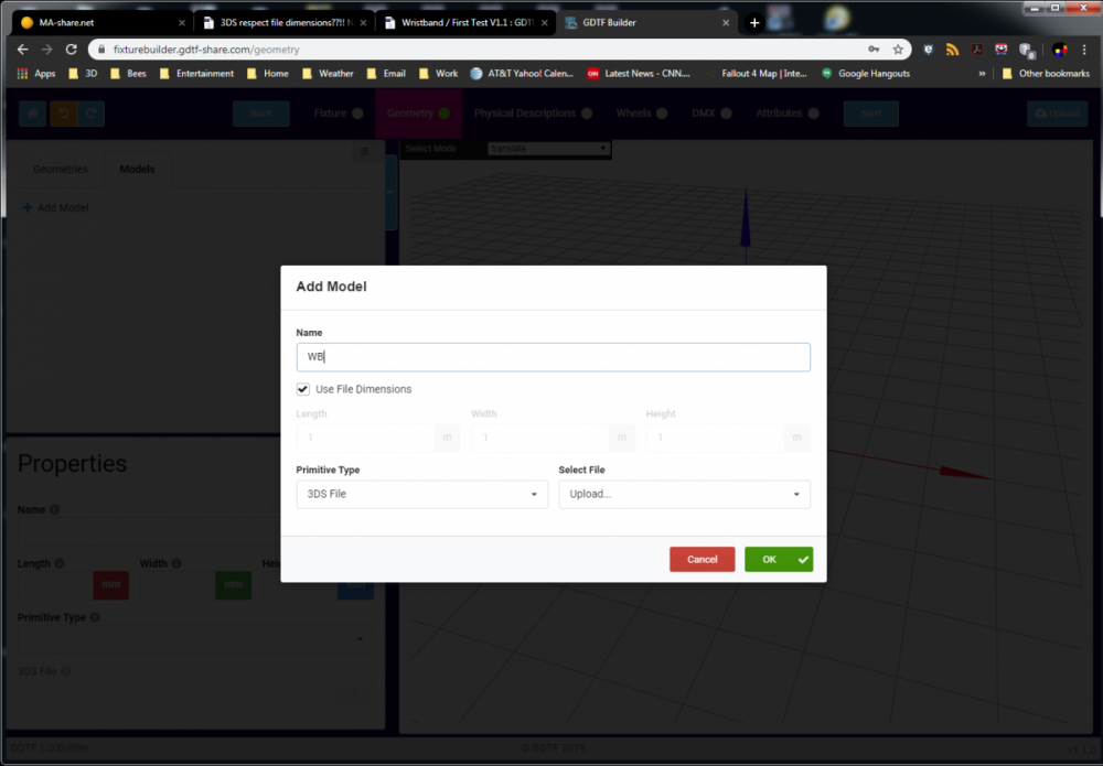
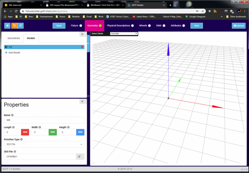
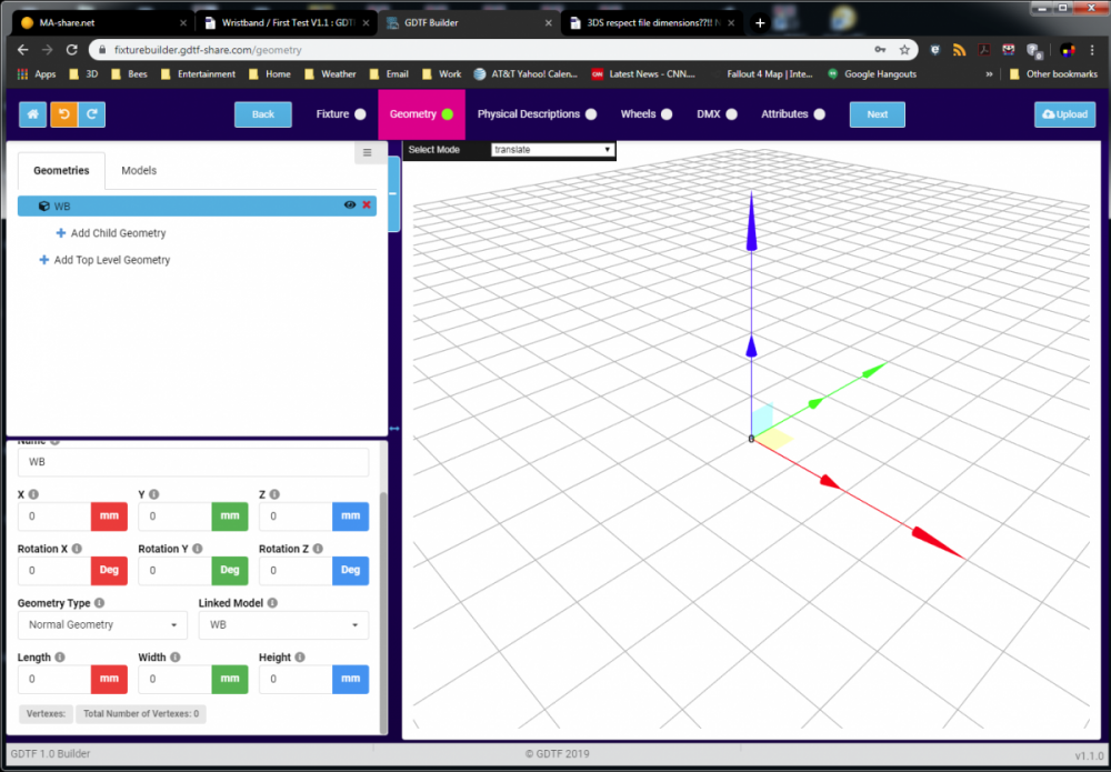
Here are my Import results from the Model Tab, the first step of the process. I've named the geometry, checked Use File Dimensions, it's a 3DS File, I'm Uploading, I hit OK. This is the resulting object with no dimension data and you can zoom into infinity and not see any geometry. If I go into the Geometries Tab and select the Existing model, I still get no dimensions...?!! Huh? and you're using C4D as your CAD tool for generating the 3DS file? I can't imagine what I'm doing horribly wrong...? I'm thinking it's in the uploading process maybe, I can't believe there are Zero Vertices in the 3DS file...?!? Which would make it indeed a non-rendering object... good thing more than one individual is working on this paradigm, ;), cause we are not all using the same programs to generate fileTypes, imho, or browsers since this is web based tool. Chrome here, U.S.A, Windows 7 machine, C4D 16[I think]...and now when I go back into the Geomery Tab, the selected geometry has a vert count??! Goofy...I've not had issues with earlier 3DS files and rendering...but now seem to. David/rex
-
Ya, the MA Lighting 3DS Importer is fairly good at respecting dimensions, irregardless of the GUI 'units' the interface is set to. Again, I say it's more 'default' to accept the file's settings....or at least parse the data to the entry fields for evaluation.
-
Observation:: When choosing an existing model from the bottom of the scroll-down menu, the Name of the file/object does not parse over to the Name entry field and you are given the default Geometry string as the name and you cannot edit it to the actual name of the file/object further[delete Model/reImport with proper Name], even though in the Model Tab of the Geometry portion, the name is correct in the Model List...?! Confusing/frustrating to try and edit the 'name' of existing geometry in the Scene.
-
Oh, and the 3D Viewport on the web based Builder does not reflect the Unit measurement[mm,cm,in,ft,m] entry fields of the input fields...