-
Posts
506 -
Joined
-
Last visited
-
Days Won
49
Content Type
Profiles
Forums
Events
Everything posted by Petr Vanek - Robe
-
Hi Pablo, you enter the values in hex, this is defined in the DIN Spec, see here all relevant sections (they are close to each other, but i linked them anyways): https://github.com/mvrdevelopment/spec/blob/main/gdtf-spec.md#rdm-section https://github.com/mvrdevelopment/spec/blob/main/gdtf-spec.md#softwareversionid https://github.com/mvrdevelopment/spec/blob/main/gdtf-spec.md#table-72-dmxpersonality In the DMX mode the software version is a version that is sent via RDM and the RDM Mode Id the ID of the mode your software sends when querying the DMX Modes via RDM. The software version linked to the dmx mode id in the GDTF builder indicates from which software is this DMX mode available in the fixture. So for you, it would be, as per the image example above: Software version 1 (taken from boot software id) and the 1, 2, 3, 4 for modes Basic, FX, Standard, Extended Hope this helps P.
-
Thank you, reported. P.
-
Hi Paolo, I think some of the issues have already been fixed and we will push then with next update but thank you for the list, this is very helpful, i will pass this to the devs. cheers Petr
-
Hello, this would indicate some network connectivity issues on your side, upload and download seem to be working OK when we are double checking it here. Kind regards Petr
-
Hi Paolo, yes, this is if you start from the empty template. If you start from another template, all is OK. We have already fixed it and will push this fix to the live Builder when we are back from LDI. Please let me know in this thread if you experience any other issues, thank you Petr
-

Beam/Shutter, Focus/Zoom on American DJ Inno Pocket Z4 won't work.
Petr Vanek - Robe replied to Druoo's topic in General
Hello, sorry, this is not the right place. You are using MA2 while this forum is about GDTF which can only be used on MA3. Please get in touch with your MA support or try using the MA forum, Kind regards Petr -
Hello. I think the issue is in the extension. If you rename it to *.3ds , then it works. Maybe you cannot even see this on the operating system of your choice... not sure. I will report this. Kind regards P.
-
Hello. Make sure that the geometry tree root is linked to your DMX Mode. Cheers Petr
-
How it should work Effect(n)Adjust(m) ?
Petr Vanek - Robe replied to Prolights's topic in Discussions
FYI, the issue has been found and is fixed, it will be part of next maintenance release of the builder. -
Hello @mhersland, we do not experience frequent crashes but we also save regularly. The builder now displays warning after 15 minutes of time with unsaved data, to help you remember to save. You should make sure that you save when you change tabs/windows for a long time and also ensure that your computer and browser is stable and up to date. What system and browser are you using? What do you see when the crash happens? Kind regards Petr
-
Thank you! Submitted as https://github.com/mvrdevelopment/spec/issues/128
-
How it should work Effect(n)Adjust(m) ?
Petr Vanek - Robe replied to Prolights's topic in Discussions
Hi @Paolo.Prolights, sorry about this, i have re-reported it again. P. -
Corect, they're not using references, I think they didn't know about it back then. We do use references pretty much all the time and we typically add custom models for the lenses too, for nicer look of the face of the device.
-
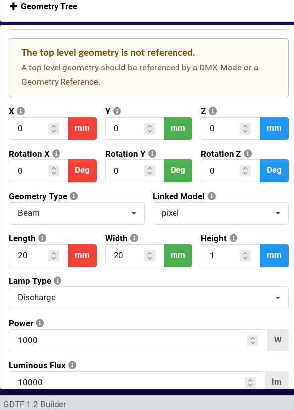
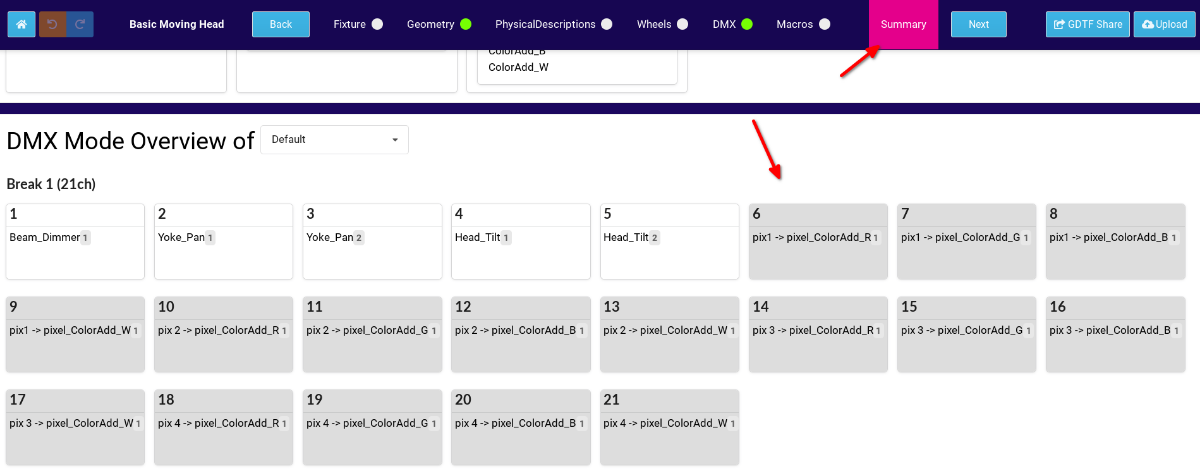
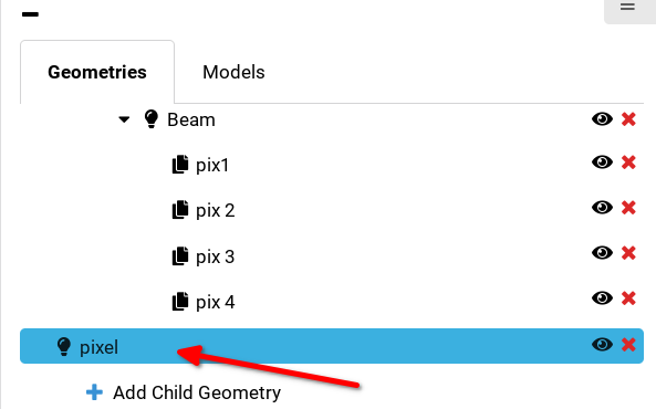
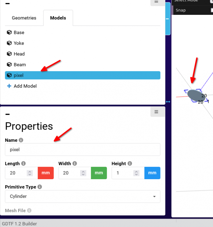
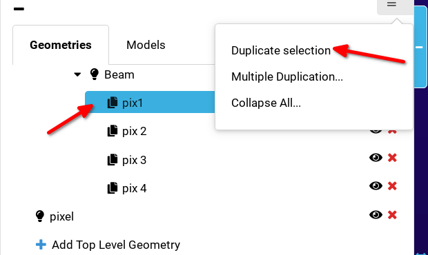
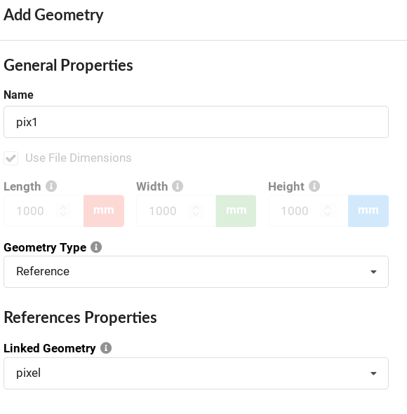
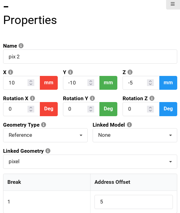
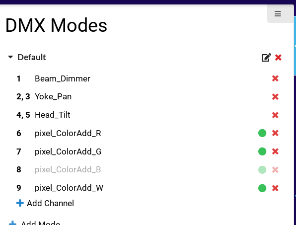
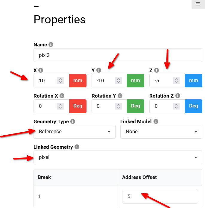
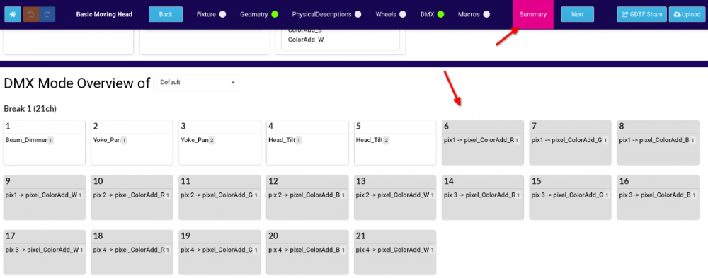
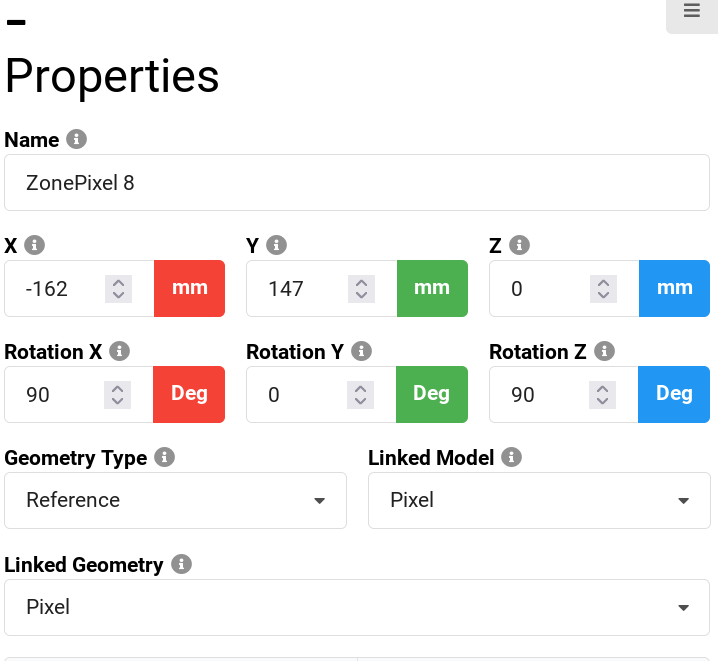
Hello @mhersland, here is what you do: First, you define your pixel. It will be a new, top level geometry: this is the model pixel You define it as a Beam: Then you go to the DMX and add DMX channels for this pixel, only once: Then, you go back to the geometry tree and add this pixel to your geometry tree (Add child geometry) as a reference: and you add it as many times to the geometry tree as many pixels you want to have... essentially, you define it once and then keep clicking the Duplicate selection, or use the Multiple duplication and enter how many pixels you want to add: (Here, i added it 4 times). Now you adjust the x and y of each of the referenced pixels1,2,3,4... you must do this manually for each pixel. You will also now define the DMX offset for each pixel: Imagine that this pixel is controlled by RGBW, that is 4 channels. So when you are editing these referenced pixels, edit not only x, y, but also edit the address offset, alway adding 4 to the previous one. First reference will be at 1, second at 1+4=5, next one at 9, next at 13...: Now, if you look at the Summary tab, you can see that we now have four pixels, each with 4 channels. This way allows us to have a nicely defined pixel and dmx channels for it, then just reference it as many times as needed. You can change the beam properties of the original Pixel in one place and it is used by the references. The Luminous Flux (if you add this value) of this pixel should be a value of the real individual single pixel. We can now also adjust DMX channels in one central place and these again, are used by the referenced pixels. The file i used for screenshots is attached here. Hope this helps P. User_Test@Pixel_references@Pixel_references.gdtf

-
Hello @mhersland, i think that what you are looking for is geometry references. This allows you to define the model just once and reference it many times. Look at some other multipixel fixtures, like some Strobes or the Spiider... hope this helps Petr
-
@anebo yes, the API exists. Please email info@gdtf-share.com for access. Hope this helps P.
-
Hi @AyrtonTerrier, sorry about the later reply. We added this to the GDTF Manual, see it here: https://gdtf-share.com/help/en/help/gdtf_how_to/key_handle_mode_dependencies.html Hope this helps Petr
- 1 reply
-
- 1
-

-
typo in Robin Spiider, Mode 10 - Pattern full RGBW
Petr Vanek - Robe replied to sl1200mk2's topic in General
Yes, that is what needs to be done. -
typo in Robin Spiider, Mode 10 - Pattern full RGBW
Petr Vanek - Robe replied to sl1200mk2's topic in General
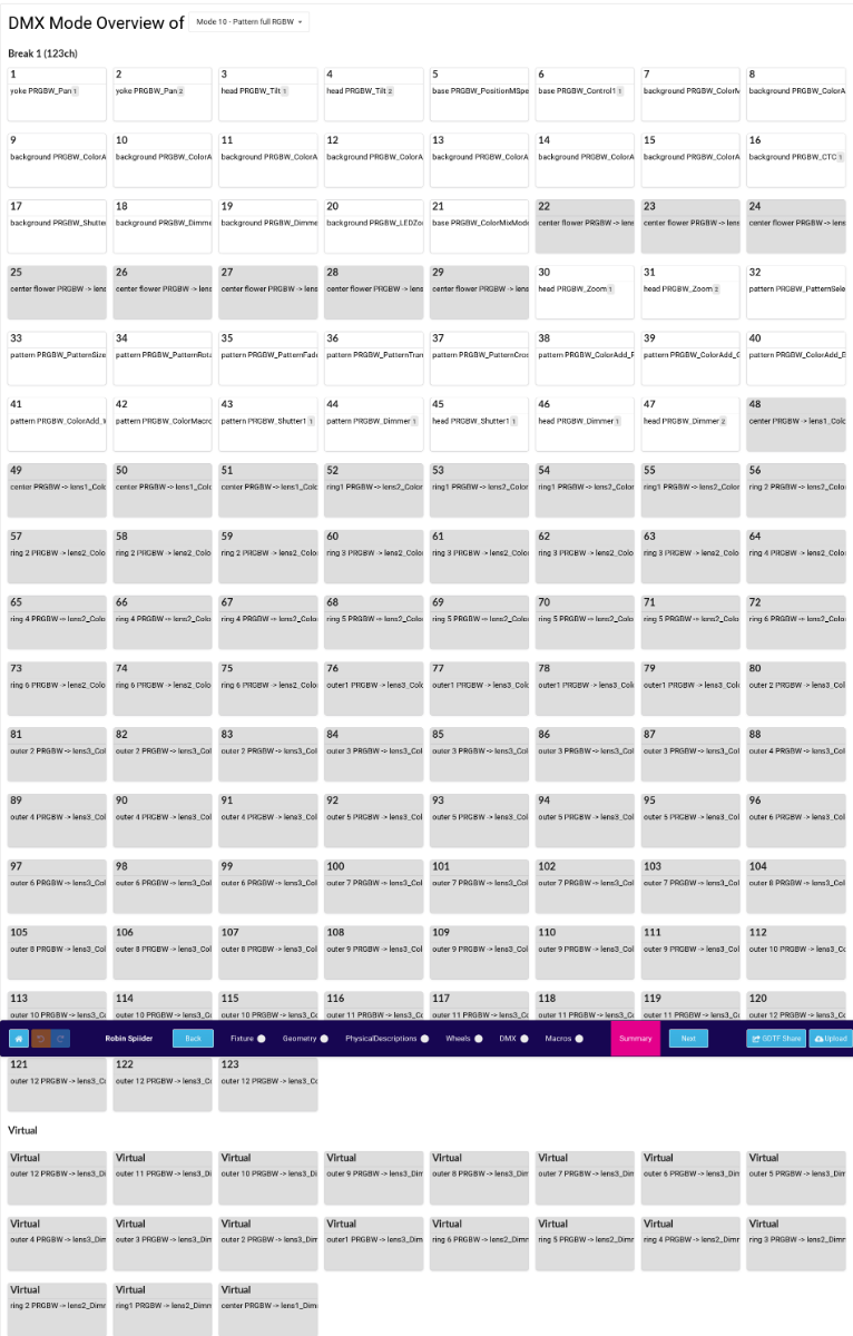
Hello @sl1200mk2, this is not a typo. These channels are defined by geometry reference of their corresponding pixels. You can see this in the overview of the GDTF builder, here is a screenshot for reference. Hope this helps, P.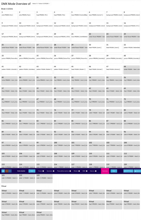
-
> In the manual it's written: To activate following functions, stop in DMX value for at least 3 seconds. > Why did you set 4s in the macros? This is because if the timing on the console is not precise (for example 2.9 sec instead of 3.0), the macro would not execute on the device We see this frequently with controllers. As 3 is the minimum value ("at least 3 seconds") , defining it 4 is OK. >also do you plan to update them for 'Power / Special Functions' offset? (offset 6) Do you mean for the rest of the Special functions? Yes, we can. >also, could you please fix the "Slow t ofast" typo 🙂 I re-reported this to our library maintainer.
-
Hi Nicolas, the T1 Profile now contains several macros: ColorControl macros (these use just one channel + timing) and also few Control macros (Display on/off) (it uses the control channel + shutter channel + time). You can see the updated file here: https://gdtf-share.com/user.php?name=Robe+Lighting+s.r.o.&page=fixtures&fixtureID=2522 Btw, there is an API for software vendors to access the share programmatically, you can email info@gdtf-share.com for access. Larger companies use this API for syncing the share to their own access server. Cheers Petr
-
Hi Nicolas, by macro i mean this: https://github.com/mvrdevelopment/spec/blob/main/gdtf-spec.md#macro-collect Does D::Light support that? I tried to figure it out but i could not find out. It is like a dynamic pallet, provided by the device file. Cheers Petr
-
Does D::Light support macros? We could add the Control Macros to our Robe device files. Please let me know, thank you Petr
-
PL&S has published their calendar, you can find GDTF related talks here (click through each day): https://pls.messefrankfurt.com/frankfurt/en/programme-events/events.html#/?day=2022-04-26&q=GDTF https://pls.messefrankfurt.com/frankfurt/en/programme-events/events.html#/?day=2022-04-26&q=MVR https://pls.messefrankfurt.com/frankfurt/en/programme-events/events.html#/?day=2022-04-28&q=15800
-
The author of the file can add this in or you can also modify the file yourself but I am not sure what the uptake is in the DMX consoles at this point for the DMX Macros.