-
Posts
429 -
Joined
-
Last visited
-
Days Won
42
Content Type
Profiles
Forums
Events
Everything posted by Petr Vanek - Robe
-
Hello @Hanz_Brech, thank you for your interest. The provided spectral data, provided in GDTF right now, are about intensity, color and color spectrum. IES files are about light/intensity distribution. What you do with the data and how you apply is completely up to you. So feel free to grab the provided files and cross compare or apply in any other way. Kind regards Petr
-
Hello @szapo, at this point, this function is not available but we are discussing it's future return. Cheers Petr cc: @dmueller
-
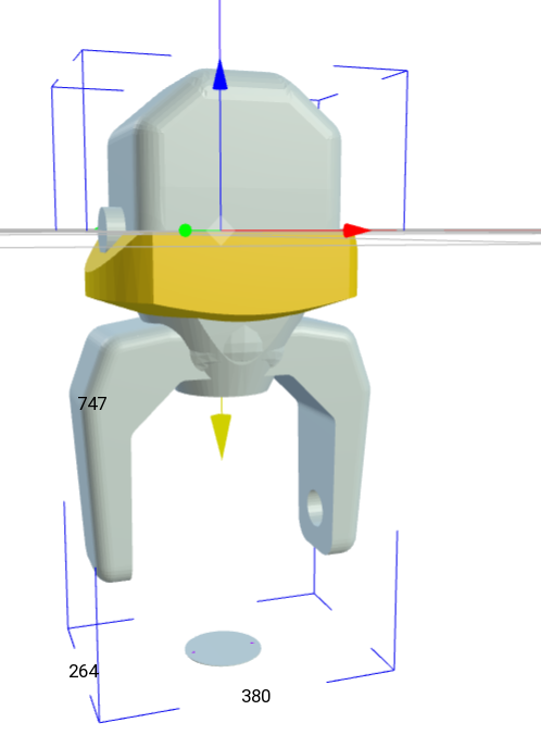
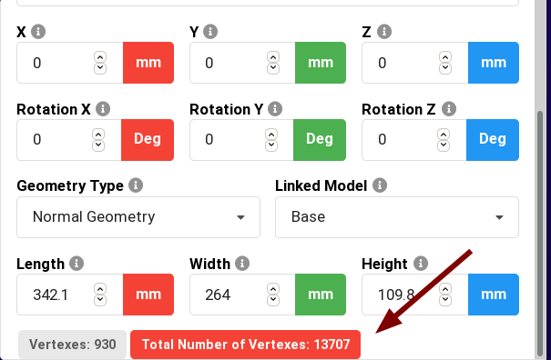
I have found some of your files @lyon470 and can see the issue with them. Models must be drawn with local coordinates at 0,0,0 and the offset (related to its parent geometry) is then given by geometry offset attribute. Typically, this is Z, negative. Your base and head are correct, but Yoke has to be modeled/moved about see image below, when offsets have been put to 0. Also, these models are huge. GDTF spec says: All models from a device combined should have a maximum vertices count of 900 to 1200. Your models in total have 13000 in some cases. Cheers P.
-
Vision implementation is very good, i would suspect an issue with the file. @lyon470what file is this? Thank you Petr
-
>Worked great now, clean, no audio. Good. ?
-
Hi David, I have re-captured it and now it is available here: http://spares.robe.cz/static/images/gdtf_video.html Hope this helps Petr
- 29 replies
-
- 1
-

-
- robe
- robe lighting
- (and 1 more)
-
Hi David, actually yes, i did, but i didn't manage to do the editing and producing it. I was not sure if this is interesting to someone, because it is quite manufacturer specific flow: have an existing model and "only" do modifications, optimizations to it, specifically to GDTF. Also, fun fact, depending on exact inside rotation of the 3D model, my "quick rotations" done via swapping axes is, while 99% the same, occasionally 90° off, meaning i must use different axes for the swap/rotate. Yes, this is Linux, i only reboot to Win when i want to see GDTF in MA3 3D or Vision, so that is a bit clumsy, although at times i use a second computer for just that, because rebooting into strange OSes is not fun. Maybe one day we'll get Linux build of MA3 :)) As for the tools i use, Freecad is really good and usable, it has quirks, but as i do not do complex editing but mostly splitting or extracting parts it is very good. So i can for example take only part of a given 3D file, like some of the front lenses, motion camera or other. The rest is done via Meshlab, where i "only" do the rotations, origin setting and mainly the mesh simplification + export. I have not found how... invested time into making this all work only in one of them or for example in Blender but there is also an issue with importing, export to 3DS and other... the workflow i have has been very fast, stable and predictable (key factors for me). The mesh simplification is a key for GDTF. It took me some time to find Meshlab which does all these things in a fast way. There is Decimate modifier in Blender, and although i have done some (mostly animation) work in Blender, i didn't try using Blender in my GDTF work flow. I am sure C4D has something similar. Mesh simplification is really important. This is because for the most, many people presume that the model has to be as precise and as "nice" as possible, while the opposite is required for 99% of the time and we have been getting a lot of heat for "your models are too complex" over the years - if you patch few hundreds of single unit with model too detailed, planning/pre-viz tools slow down to crawl... I am sure there are custom projects where one wants to build a real-world render with textures, smooth models... and, GDTF is extensible enough to make it possible to use for that and even more in the future (for example by allowing multiple versions of models, adding textures...) , but the initial focus has been on the most required work-flow, so our [Robe] model optimizations are hitting exactly that. ? P.
- 29 replies
-
- 1
-
-
- robe
- robe lighting
- (and 1 more)
-
 Hi Matt, > I know we are adding in really awesome vaidation features, but over time it shouldn't really break thing's that have already been pre-defined when pushing new builds online This is not really about syntactical stuff but rather about cross checking, for example when assigning Wheel slots into DMX Sets, but not assigning a Wheel to the Channel Function, which a user error, rather then syntax issue, but it of course is much better to indicate in the builder if something is missing while doing the editing. As i mentioned, it is where the practical implementation allows us to see that some parts are not filled in by the user. And based on that, we have been extending the validations. The required changes are typically very small, considering the possible complexity of the complete GDTF file if fully filled up. So, sorry about it, progress... ? Cheers P.
 -
Hi Matt, >That is very unfortunate Sorry about this. >so, is there a plan for the future if you have to check over 100+ files that you shouldn't have to do that.....? Absolutely, this is why a huge effort was put into the validation as it is now. Having said that, as the actual implementation in software has progressed dramatically, there will be an update to the specification itself in near future, bringing up more, new features/clarifications, so this might mean more edits for the older files if you like to add some of the new additional data. But these will all be details, the core remains. cheers P.
-
Hi Matt, yes. The old builder provided the same way to enter this info but less way to check if you didn't forget anything or made any error. So it is useful to go through all previously made files to double check for errors. And yes, also for us, it meant full re-checking on all files...¯\_(ツ)_/¯ but this is actually typically very quick. If you don$t know what is wrong, use also the Summary Tab, where you get errors listed together with their causes. cheers Petr
-
Problems with visualization in GMA3 viewer
Petr Vanek - Robe replied to MK Eventtechnik's topic in General
@MK Eventtechnik Please look at the attached screenshot. You have two beams, distanced from each other. Also, each is pointing different direction (the yellow arrow shows where the beam is pointing). Hope this helps P.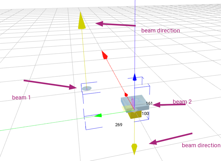
-
Problems with visualization in GMA3 viewer
Petr Vanek - Robe replied to MK Eventtechnik's topic in General
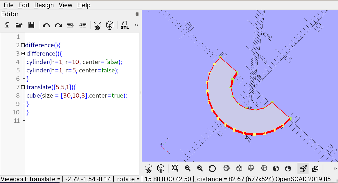
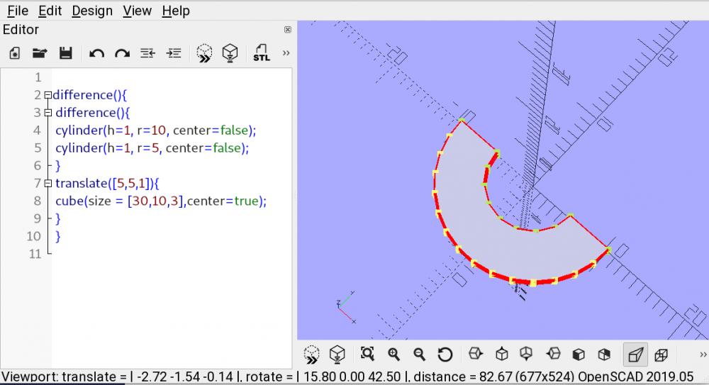
Actually, for rings, either you make them or can use the ones in builder, see screenshot below. Or you can make them, either in regular CAD or in things like openscad, export and convert to 3DS in something like meshlab... (see openscad example below).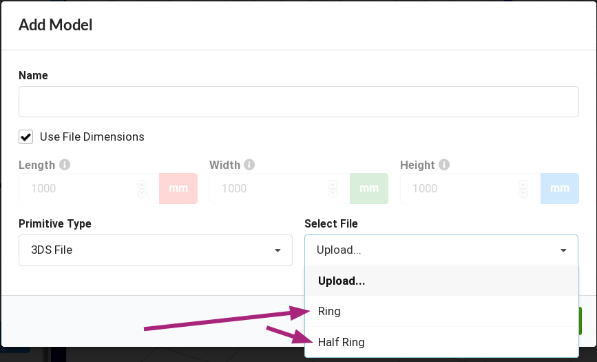
-
Problems with visualization in GMA3 viewer
Petr Vanek - Robe replied to MK Eventtechnik's topic in General
Hello @MK Eventtechnik if you define the rectangle's beam geometry not as a Spot or a Wash but as None, it will not make any beam, but will glow when looking into the beam. Hope this helps Petr -
Hello @MK Eventtechnik if you want to have it rotated, the base geometry needs to be modeled that way as the base defines complete positioning of the whole model, because if you rotate it, X,Y and Z are suddenly not really defined correctly. The complete orientation can always be changed by the used inserting the fixture to visualizer according to their needs. Kind Regards Petr
-
To clarify: the builder's backend server is at the moment NOT being used to verify the file during upload to the share directly from web browser, but the plan is to do this (i was living under the impression that this was deployed already).
-
>Presumably all axis geometries are to be drawn at "home" Hmm, we should probably specify, so it is clarified, rather then presumed. The orientation of yoke to base is important, as you say. But the orientation (not position, that is important) of the base in the 3D space does not really matter in my understanding as long as the pigtail indicates it's "true" orientation (front/back). >should have their base drawn at an angle Either the base of the yoke. Their relation to each other is important.
-
Let me add here, that lots of the extensive validation work has been part of some of the recent, now available revision of the builder (or the backend library, respectively). So previously made files can show "errors" that were not observable (by the builder) before. These are. as usual, marked red in particular sections and the Summary tab of the builder now lists of all these errors, with their description.
-
Hi Lars, technically, i believe we use the same backend used by the builder, to parse the library during upload. cheers P.
-
The data in the editor is being processed server side on the builder backend. Not necessarily stored permanently, but there is the shorttime period when this happens. Nobody is watching this data, but from technical perspective, the server is involved. At this point, there are discussions about how to make this better for manufacturers, but at the same time, we want to make sure that the free to use builder is also providing useful data back to users.
-
GDTF-Share--->Fixture Builder????
Petr Vanek - Robe replied to David "Rex" Whalen's topic in General
Hi @David "Rex" Whalen, Can you perhaps post info from the developer console of your browser? This is invoked by F12, then select "Console" tab. Errors would be red, so you can see them well. The builder is not flash based, this is pure HTML5 application. You may try to disable add-ons (in your browser), perhaps something is colliding (for me it does work with UBlock Origin). Cheers -
Dear @costa, i don't think so... look: https://gdtf-share.com/gdtf.php?page=home&query=strip&man=1&fix=1&rev=1&use=0 Kind Regards Petr
-
GDTF-Share--->Fixture Builder????
Petr Vanek - Robe replied to David "Rex" Whalen's topic in General
Just tried on Windows 8 Pro (Chrome, Firefox), all without issues, our GDTF person is using it daily from Win10 systems and i use it daily from my Debian Linux with Firefox (Chrome, Chromium also tested) without any issues. -
Yes, orientation of the axis is given, which allows for moving heads but also for moving mirrors to work. We clarify this a bit more in 1.1 for moving mirrors (scanners). The pigtail position then indicates the real (cable connection) position, giving you the true orientation of the device. See our fixtures, their pigtail is in correct place in relation to pan/tilt movement. Also the SilverScan works well in visualizers, thanks to it's default "stand up" orientation, aligning the axes "correctly".
-
Yes, Rex is correct, the pigtail is to indicate the orientation for correct model→real device alignment.
-
Strange. Do right click → Save link as. I will upload it to YouTube or Vimeo. Anyways, i made a small mistake (didn't rotate the head one more time) so had to do a bit of time travel via copy/paste while editing, so am thinking to re-capture it, that is why i didn't upload it to any of the platforms yet...
- 29 replies
-
- 1
-
-
- robe
- robe lighting
- (and 1 more)