Help Pages

Geometry Page

In this section, the physical and logical structure of the device is defined.
The physical structure represents which parts of the device are mechanically connected to each other. The logical structure represents logical dependencies between parts of the device that are needed to describe functions of the device.

A valid GDTF file must have at least one geometry. A geometry can contain a link to a 3D model.

Geometries/Models Section

The left part of the Geometry Page shows the Geometries/Models section. In the Geometries section, all geometries are listed in the form of a tree structure. The Models section contains a list of all models that are currently part of the GDTF file.

Clicking on the - icon collapses this section and provides more space for the Properties section.
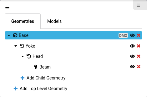
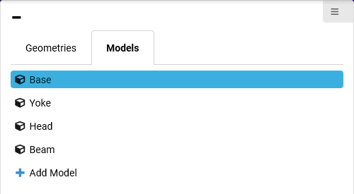
Typical geometries and models of a simple moving light
  • To add a new geometry or model, select + Add Geometry or + Add Model.
  • To move a geometry within the tree structure, just drag and drop it at the new position. Dropping a geometry onto an existing geometry creates a child geometry.
  • To hide a geometry in the 3D view, click the 👁️ icon.
  • To delete a geometry or model, click the X icon.
Only unused models can be deleted.

Properties Section

The Properties section is located below the Geometry Tree section. All properties of the currently selected geometry or model can be viewed and edited here.

Information about the vertices count of the selected geometry and of all geometries can be found at the bottom of the Properties section.

3D View

The right part of the Geometry Page shows a 3D view of the device.
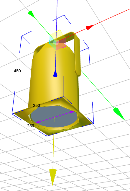
  • The grid represents the zero level (XY plane).
  • The long colored arrows represent the global coordinate system with X (red), Y (green) and Z (blue) axis.
  • To rotate the 3D view around the center of the the current view, click and drag with the left mouse key.
  • To move the view horizontally or vertically, click and drag with the right mouse key.
  • To zoom in and out, use the mouse wheel.
  • To select a geometry, click on it with the left mouse key. Selected geometries are highlighted in yellow.
3D view of a generic PAR can

Selected geometries can be moved and rotated using the colored handles.

  • To move or rotate a geometry on one axis, drag it using the coordinate handles.
  • To move a geometry on a specific plane, drag it using one of the colored squares.
  • To move a geometry freely in space, drag it using the small white cube in the origin of its coordinate system.

A blue bounding box is displayed for the currently selected geometry and all of its children. The numbers on the edges indicate the current dimensions (in mm) of the selection.

Yellow arrows are drawn for each Beam geometry. The direction of the arrow indicates the direction of the Beam. Purple arrows on a Beam geometry indicate the Beam Diameter.

The 3D view does not render any textures that are mapped to 3D models.

3D View Settings

The 3D View Settings are located in the top-left corner of the 3D View.

  • The Renderer Mode setting changes the displayed level of detail for 3D models.
  • The Select Mode switches between movement handles and rotation handles.
  • To make geometries snap at their bounding boxes, enable the Snap option.