Each DMX Channel in GDTF holds one or multiple Logical Channels. While the DMX channel contains information like the DMX address(es) and resolution, the Logical Channel(s) describes the actual function(s).
When creating a channel which controls multiple functions, you need to decide whether to
- create one Logical Channel with multiple Channel Functions,
- create multiple Logical Channels with one Channel Function or
- create multiple Logical Channels with multiple Channel Functions.
To help you with this decision, have a look at the examples in this table:
| Functions of the channel |
Characteristics |
Recommended Structure |
Shutter
ShutterStrobe
ShutterStrobeRandom
ShutterPulseClose
ShutterPulseOpen |
Multiple functions of the same main attribute (Shutter) and the same Feature Group (Beam), which the user expects to control in the same place |
One Logical Channel with multiple Channel Functions |
Shutter
Dimmer |
Functions of different main attributes (Shutter vs. Dimmer) and different Feature Groups (Beam vs. Dimmer), which the user expects to control in different places |
Two Logical Channels with one Channel Function each |
By default, a newly created DMX channel has one Logical Channel and one Channel Function.
This chapter describes how to create multiple Logical Channels within a DMX channel.
Starting point
Our fixture we want to describe has a combined Dimmer + Shutter channel with the following ranges:
| DMX value |
Function |
| 0...139 |
Dimmer 0...100% |
| 140...255 |
Shutter Strobe 1...20 Hz |
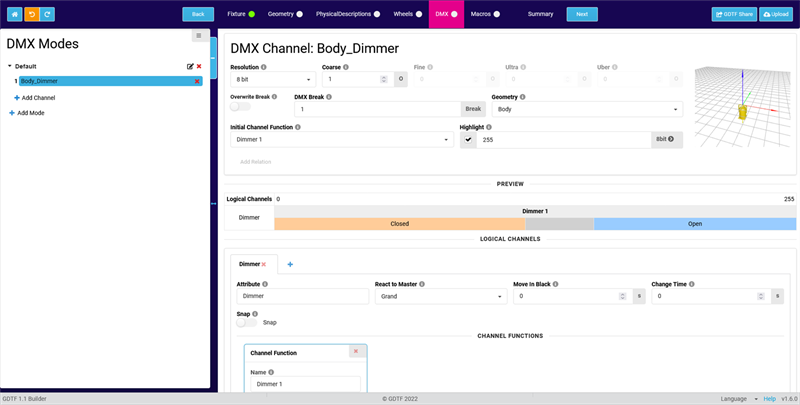
There is already a Dimmer channel which looks like this:
Adding a second Logical Channel
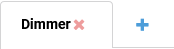
- Click on the + icon next to the Dimmer tab.
The Add New Logical Channel pop-up opens.
- Click in the Attribute field. The Select Attribute pop-up opens.
Search for the Shutter(n) attribute, select it and confirm both pop-ups by clicking OK.
Configuring the Shutter Logical Channel
- As we want to describe a Strobe function, change the Attribute of the Channel Function to Shutter(n)Strobe.
- The physical units of the Channel Function have now changed to 1/s (Hz). Change the Physical From value to 1 and the Physical To value to 20.
- According to the DMX chart of our fixture, the Shutter function is only active between a value of 140 and 255. Below 140, the Dimmer is being controlled.
So we need to add a No Feature Channel Function to our Logical Channel, which covers the range from 0 to 139.
Click on the + Symbol left of the Channel Function and select "NoFeature" as attribute in the pop-up.
- Set the DMX From value of the Shutter Channel Function to 140. The DMX To value of the NoFeature Channel Function will be automatically adjusted to 139.
- Set the Default DMX value of the Shutter Channel Function to something between 140 and 255.
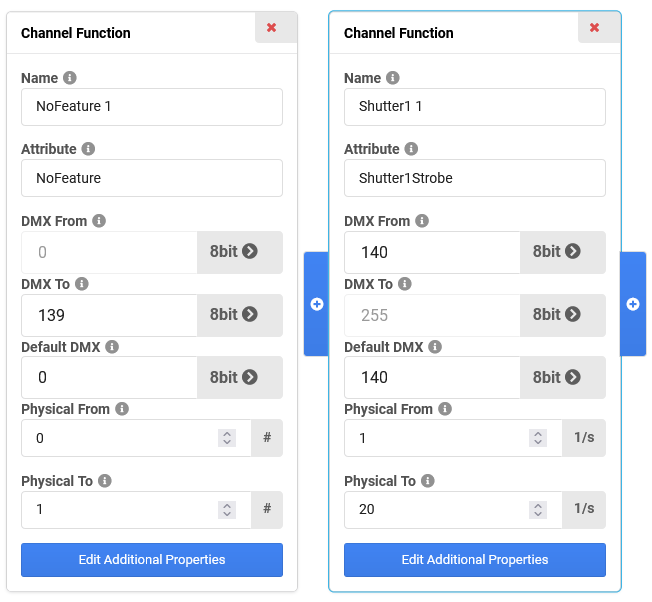
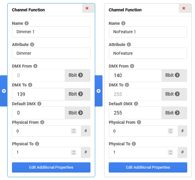
Now both Channel Functions should look like this:
Configuring the Dimmer Logical Channel
- Go back to the Dimmer Logical Channel by clicking on the Dimmer tab in the Logical Channels section.
- As the Dimmer is only controlled in a range from 0 to 139, we need to add a NoFeature Channel Function here as well, which covers the range from 140 to 255.
Click on the + icon right of the existing Channel Function and select again "NoFeature" as attribute in the pop-up.
- Set the DMX From value of the NoFeature Channel Function to 140. The DMX To value of the Dimmer Channel Function will be automatically adjusted to 139.
- You might get an error message because the "Open" Channel Set of the Dimmer Channel Function has a value of 255, which is not within the range of the Channel Function. You can adjust the DMX From and DMX To values of the "Open" Channel Set to 139.
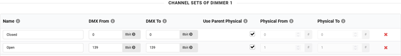
- Now both Channel Functions should look like this:
- The Preview section now shows both Logical Channels as well:
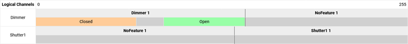
The partition of the Preview section does not resemble the real ranges of values!
So in this case, everything is correct, although the split between attribute and NoFeature is not at the same position for both Logical Channels.